

01 / APPLICATION OVERVIEW
Cement Plant Steel Grating for Heavy Loads and Safe Access
Cement plant steel grating provides load-bearing walking surfaces for equipment platforms, maintenance routes, and stairways exposed to dust, vibration, and demanding industrial service.
Typical locations include crusher platforms, raw mill access areas, conveyor galleries, kiln service platforms, and cement grinding sections. Grating provides access for inspection, lubrication, and component replacement while allowing rainwater and some loose material to pass through the openings. Platform layouts should accommodate maintenance tools, equipment removal routes, and designated lifting areas.
Selection requires defined pedestrian loads, concentrated maintenance loads, support spans, bearing bar direction, and allowable deflection. Engineers should also assess vibration, abrasive dust, corrosion exposure, walking surface, and panel retention. Heavy components, trolley wheels, and temporary equipment storage require specific load checks rather than selection by bearing bar dimensions alone.
Discuss Your Walkway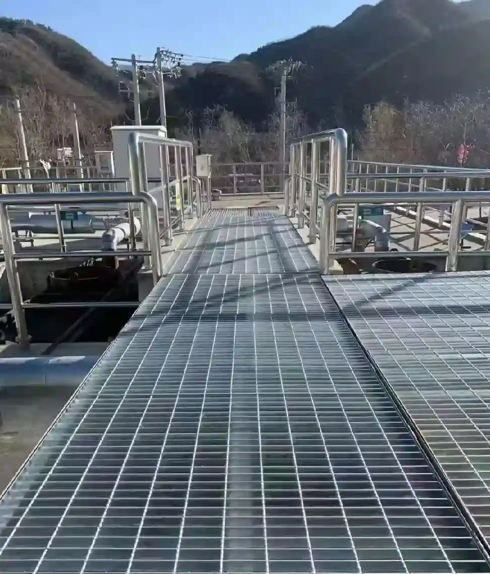
02 / APPLICATION SCENARIOS & REQUIREMENTS
Application Scenarios & Project Requirements
Review the operating conditions, users, loads, environment and project requirements before selecting the appropriate steel grating specification.
Crusher Maintenance Platforms
Grating platforms provide access around crushers, feeders, and transfer equipment for inspection and servicing. Bearing bars and supports must accommodate the specified personnel, tools, and maintenance loads, with separately designed areas where heavy wear parts are handled or temporarily placed.
Raw Mill and Grinding Access
Steel grating supports walkways around raw mills, cement mills, separators, and associated drives. Panel layouts should provide access to inspection doors, lubrication points, and service equipment while keeping removable sections manageable and maintaining clear routes through congested process areas.
Conveyor Gallery Walkways
Grating walkways along belt conveyors allow personnel to inspect idlers, belt tracking, and transfer points. Open panels facilitate drainage in exposed galleries, while surface selection and housekeeping must address cement dust, spilled material, and wet deposits that can reduce footing.
Kiln and Preheater Service Platforms
Grating provides access around kiln equipment and preheater structures where inspection routes extend across multiple elevations. Design should account for local temperatures, thermal movement, equipment vibration, and maintenance loads, with coating suitability assessed for the actual exposure at each platform.
03 / SPECIFICATIONS & PRODUCT OPTIONS
Common Specifications & Available Options
Compare materials, bearing bar sizes, spacing, surface types, finishes and panel dimensions to match the requirements of the application.
Specifications
| Parameter | Specification / Options |
|---|---|
| Material |
Weldable carbon steel, commonly Q235B, Q355B, ASTM A36, or ASTM A572 Grade 50 where specified and accepted by the project. State the required material standard and grade. These grades are separate specifications and should not be treated as automatically interchangeable. |
| Surface treatment |
Hot-dip galvanized after fabrication for suitable outdoor and humid service; project-specified painted or uncoated steel may be used where temperature or process conditions require a different finish. Confirm exposure to heat, alkaline deposits, cleaning chemicals, and abrasion before selecting the coating. |
| Bearing bar size |
Common access-platform options include 25 × 3, 30 × 3, 30 × 5, 32 × 5, and 40 × 5 mm. Heavier sections can include 50 × 5, 50 × 6, 60 × 6, 65 × 6, and 75 × 8 mm, subject to supplier capability and engineering verification. Bar depth × thickness. Load capacity depends on material, clear span, bar spacing, surface profile, and load distribution. |
| Bearing bar spacing |
Common center-to-center pitches include 30, 30.16, 34.3, and 40 mm. Closer pitches such as 20 mm may be specified for particular access or small-object retention requirements. Select one defined pitch for each panel type. Clear opening equals pitch minus bar thickness and must satisfy the project access criteria. |
| Cross bar spacing | Common center-to-center pitches include 50 and 100 mm; supplier series may also use 50.8 or 101.6 mm. Welded or pressure-locked construction should be identified in the specification. |
| Panel dimensions |
Illustrative panel dimensions include 600 × 1,000, 800 × 1,200, 1,000 × 1,000, 1,000 × 1,200, and 1,000 × 3,000 mm, with fabrication to approved layout drawings. State bearing bar length and panel width separately. Panel length does not establish the allowable unsupported span; intermediate supports may be required. |
| Walking surface |
Plain or serrated bearing bars. Serrated profiles may be specified for exposed routes or areas with dust and moisture. Verify load data for the selected serrated section. Surface profiling does not eliminate the need to remove accumulated cement, oil, or wet deposits. |
| Stair tread dimensions |
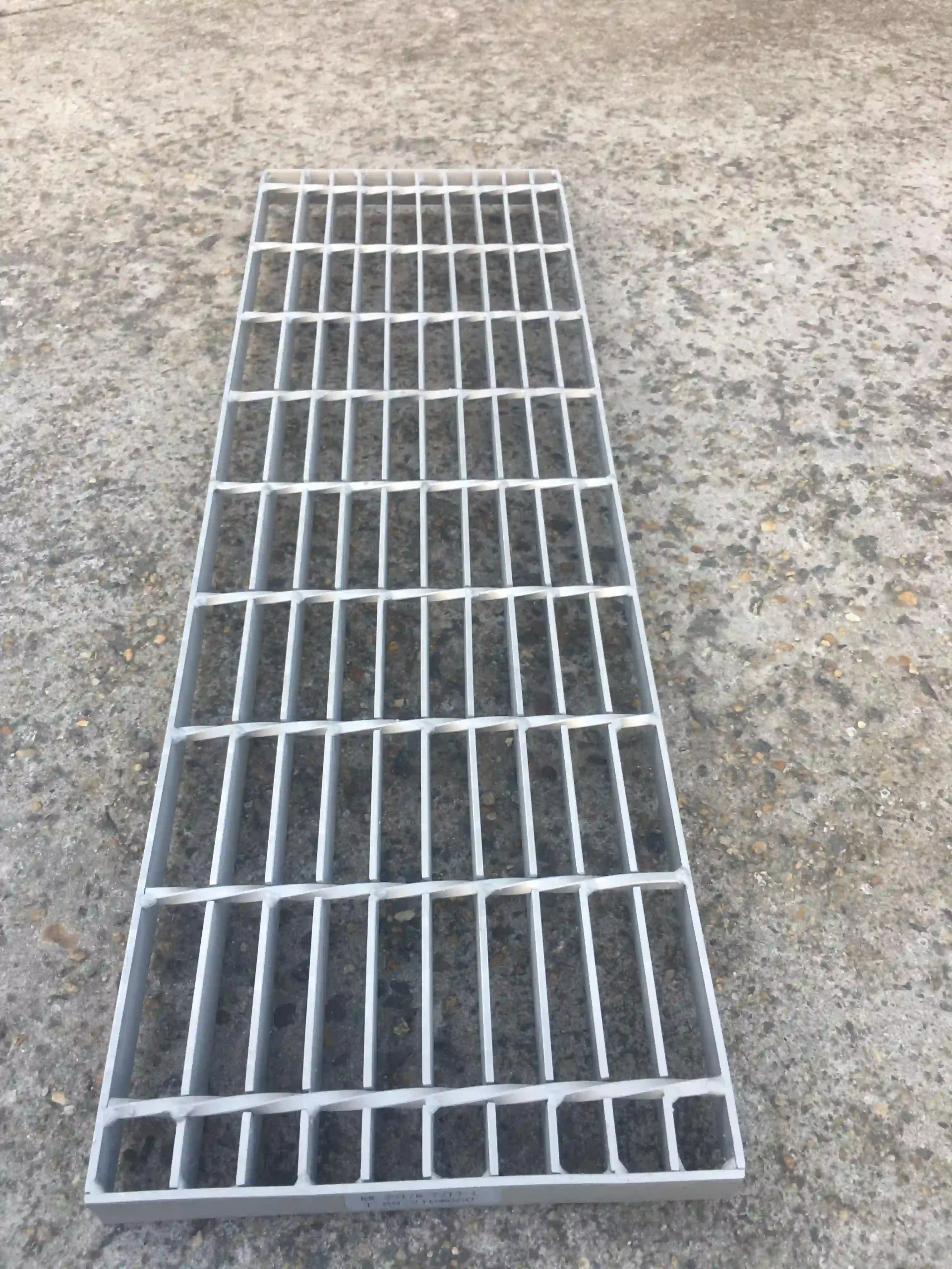
Common fabrication examples include widths of 600, 800, 900, 1,000, and 1,200 mm, with front-to-back depths around 240, 270, or 300 mm. Bolted end plates and defined anti-slip nosings can be supplied. Final tread depth, rise, width, and connections must match the approved stair design and applicable access requirements. |
| Edges and openings |
Banded panel edges, reinforced equipment cut-outs, and project-specified toe plates. Pipe penetrations, access openings, and removable sections are dimensioned from approved drawings. Cut bearing bars may require additional support or reinforcement. Toe plates and opening protection follow the platform safety design. |
| Fixings and retention |
Project-specified grating clamps, bolted retaining plates, or welded connections. M8 and M10 bolts are common fixing options where compatible with the selected clamp and support detail. Fixing quantity, location, tightening requirements, and resistance to vibration or uplift must be defined by the connection design. |
| Load and bearing direction |
Bearing bars span between supporting members. Confirm clear span in mm, uniformly distributed load in kN/m², concentrated load in kN, load contact area, and allowable deflection in mm. Check wheel loads, heavy spare parts, impact, and equipment handling separately. Specify minimum end bearing and support details on the drawings. |
Need a different size? Send your layout for a custom panel review.
Request Your SpecificationThe sizes above are reference examples, not approved combinations for every span. Confirm the bearing direction, loads, clear span and material before ordering. Panel size does not indicate the allowable unsupported span.
WHY USE STEEL GRATING?
Advantages for Steel Grating Applications
Load-Specific Bar Selection
Bearing bar depth, thickness, and spacing can be selected for the platform’s actual span and maintenance loads. This allows access routes and designated heavy-service areas to use sections appropriate to their different duties.
Drainage Through Open Panels
Open grating allows rainwater to drain from exposed conveyor galleries and service platforms. It reduces water retention where openings remain clear, although compacted cement deposits still require removal to preserve drainage and footing.
Serrated Surface Option
Serrated bearing bars provide additional surface edges for footwear contact on routes exposed to dust and moisture. Their suitability should be assessed with site conditions, cleaning practices, and the load capacity of the selected profile.
Protected Outdoor Steelwork
Hot-dip galvanizing can protect fabricated panels in suitable outdoor and humid areas. Selecting the finish for local heat, chemical exposure, and abrasion helps maintain serviceability across different sections of the cement plant.
Removable Maintenance Sections
Individually retained panels can provide planned access to equipment beneath a platform. Defined removal points, panel identification, and manageable panel weights support servicing while allowing damaged sections to be replaced independently.
Fit Around Process Equipment
Drawing-based fabrication accommodates columns, chutes, ducts, and service penetrations. Coordinated panel joints and reinforced openings help preserve support continuity and reduce uncontrolled cutting during installation around existing plant equipment.
04 / INSTALLATION & PROJECT PHOTOS
Installation Guidance & Application Photos
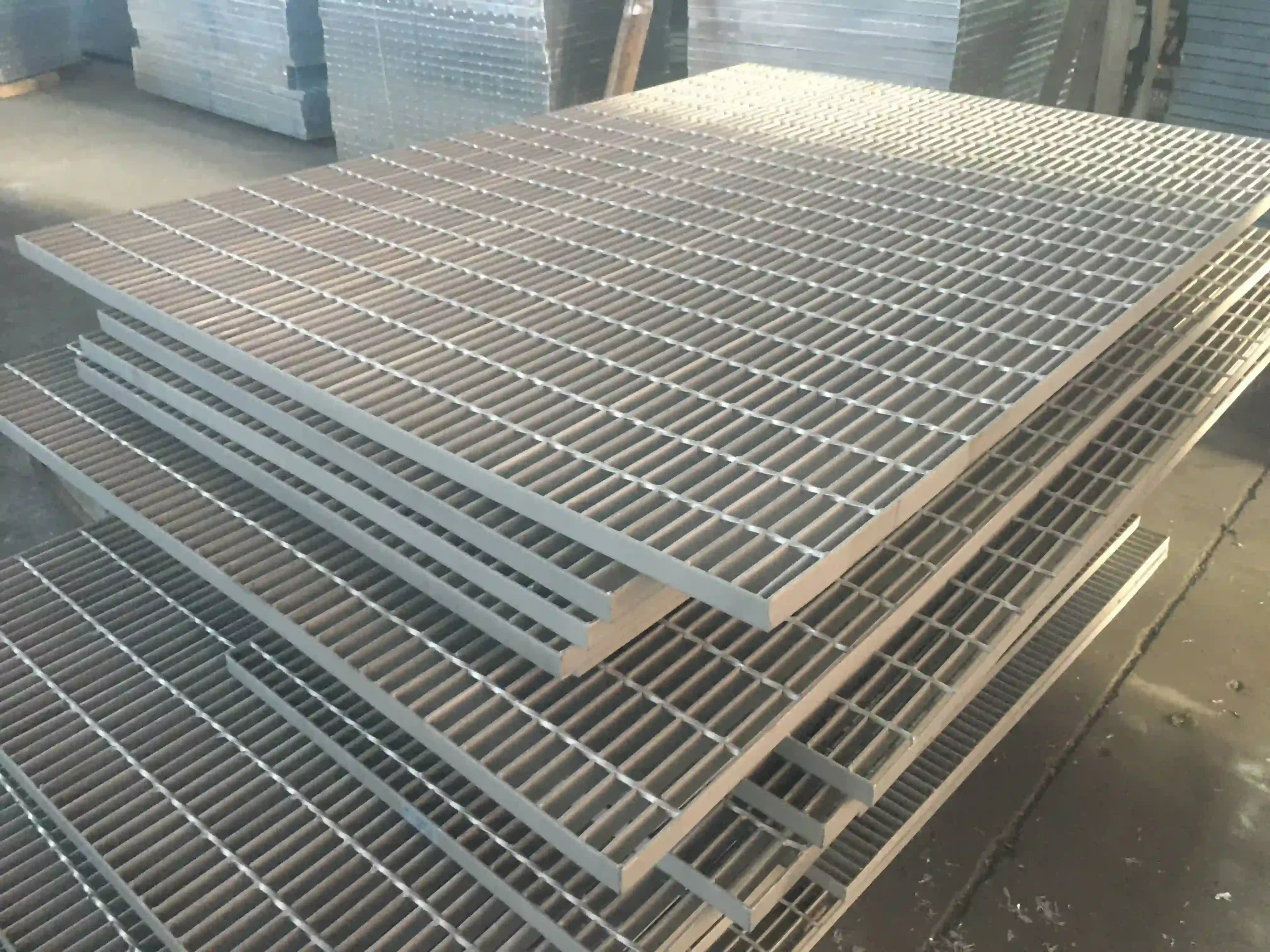
Review the panel layout, support conditions, fixing methods and fabrication details before installation, and refer to the application photos for practical examples.
-
Verify Supports and Design Loads
Check support locations, elevations, clear spans, and required end bearing against the approved drawings. Confirm the specified pedestrian and maintenance loads, including any designated component-handling areas. Complete the site’s isolation and access controls before working near operating equipment.
-
Place Panels in the Approved Direction
Match panel identification to the layout and orient bearing bars across the designated supports. Check joints, stair transitions, equipment clearances, and cut-out reinforcement. Obtain design approval before cutting bearing bars or changing support positions.
-
Secure Panels and Restore Coatings
Install the specified clamps, retaining plates, or welded connections at the approved locations. Use the required tightening procedure and vibration-resistant details. Repair damaged coatings using the project-approved method, and confirm that removable panels remain securely retained during service.
-
Inspect and Release the Access Route
Check for rocking panels, unsupported edges, loose fixings, sharp projections, and obstructed drainage. Verify toe plates, guardrails, and opening protection before use. Establish routine inspections for cement buildup, corrosion, wear, and fixing movement, especially near vibrating machinery.
05 / RELATED REFERENCE & FAQ
Frequently Asked Questions
What determines the load capacity of cement plant steel grating?
Capacity depends on bearing bar section, material grade, spacing, clear support span, and load distribution. A panel carrying personnel may need a different design from one supporting maintenance trolleys or heavy spare parts. Selection should use verified load tables or calculations that address both strength and allowable deflection for the specified loading conditions.
Which bearing bar sizes are suitable for heavy maintenance loads?
Sections such as 40 × 5, 50 × 5, 50 × 6, 60 × 6, or larger bars may be considered, but no size is suitable for every span or load. Provide the concentrated load, contact area, support spacing, and deflection limit. Heavy component storage or wheel traffic may require closer supports or a separately designed platform area.
Should cement plant walkways use plain or serrated grating?
Serrated grating is often considered where rain, dust, or moisture affects footing. Plain grating may suit controlled areas after assessment of operating conditions. Neither surface prevents slipping when coated with oil or compacted wet cement. Specify the required surface, verify its load data, and include regular cleaning in the access maintenance plan.
Is hot-dip galvanized grating suitable near kilns and preheaters?
Suitability depends on the actual panel temperature and exposure, including radiant heat and hot process releases. Hot-dip galvanizing can serve many general plant areas, but elevated temperatures require a specific coating assessment. Provide normal and peak temperatures so the designer can select an appropriate finish and assess thermal movement and material performance.
How should grating panels be retained near vibrating equipment?
Connections should be designed for the expected vibration, panel movement, and any uplift forces. Specified clamps or retaining plates must engage the supporting steel securely and use suitable fastener retention. Fixing quantity and location depend on the panel and support arrangement. Inspect connections periodically, particularly around crushers, screens, mills, and conveyor drives.
What information is needed for a cement plant grating quotation?
Provide panel layout drawings, quantities, bearing direction, support spans, design loads, material grade, bar sizes and spacing, surface profile, and coating requirements. Include equipment cut-outs, stair treads, toe plates, fixing details, and removable sections. Identify wheel traffic, heavy maintenance loads, high-temperature areas, and corrosive exposure so these conditions can be addressed before fabrication.
06 / PROJECT ENQUIRY
Tell Us About Your Walkway
Share your layout and operating requirements so our team can review the grating, fabrication and supply scope.
Send Drawings by Email Discuss on WhatsAppThe email button opens your mail app. Attach your drawings before sending.
Include these details
- Application location and exposure conditions
- Drawings, panel dimensions and quantities
- Support layout, clear span and design loads
- Material, finish and walking-surface requirements
- Cut-outs, fixings and removable access sections
- Destination, required delivery date and project standards
Already have a specification? Send it with your enquiry.