

01 / APPLICATION OVERVIEW
HDG Grating Walkways for Photovoltaic Power Generation
HDG grating walkways provide durable access routes for inspection and maintenance work throughout outdoor photovoltaic power generation facilities.
These walkways are installed between PV arrays, around inverters and electrical equipment, and on elevated service platforms to support routine module inspection, cable servicing, cleaning, and equipment maintenance.
Selection should consider the support span, design load, bearing bar direction, walking surface, panel layout, fixing method, drainage requirements, and long-term exposure to moisture and corrosive outdoor conditions.
Discuss Your Walkway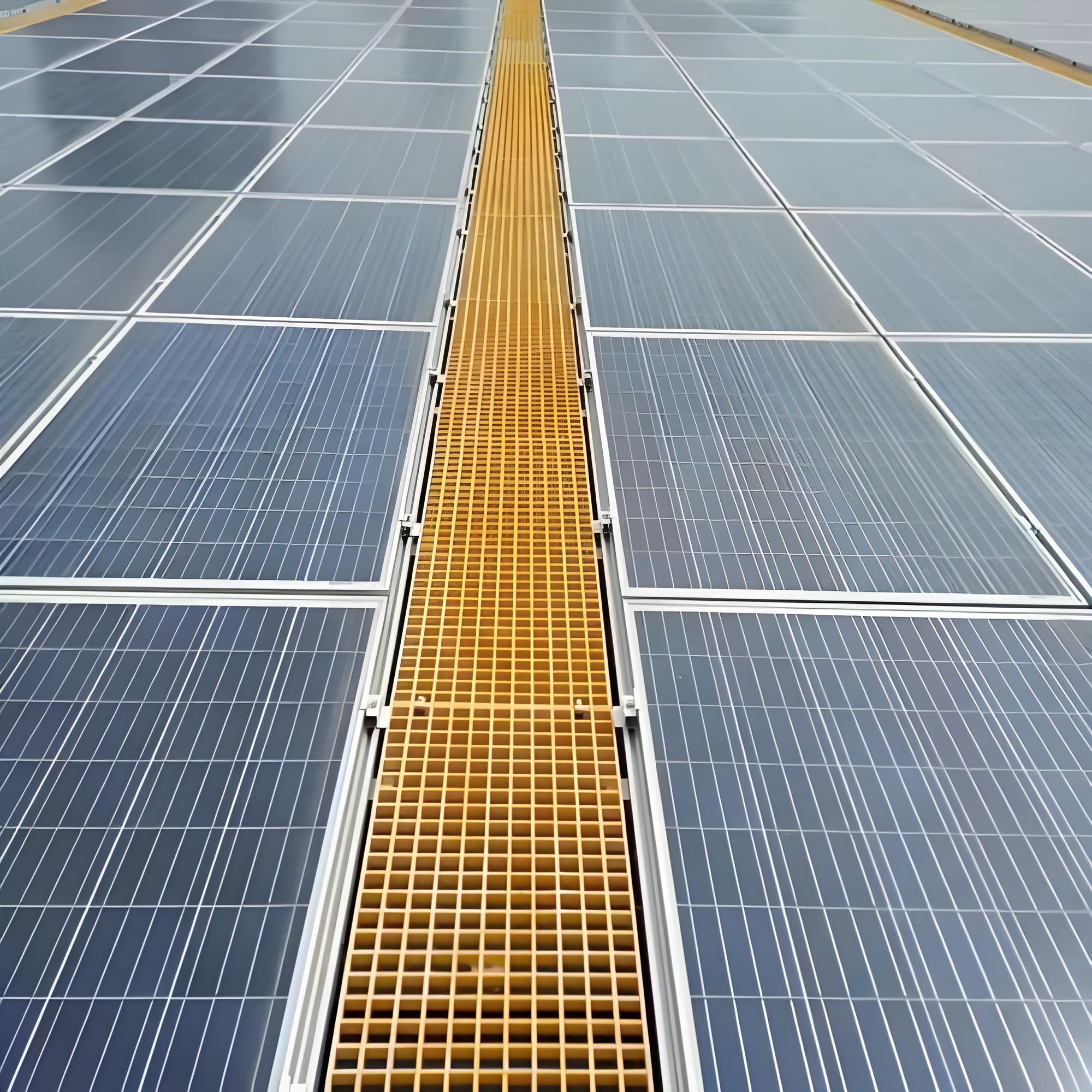
02 / APPLICATION SCENARIOS & REQUIREMENTS
Application Scenarios & Project Requirements
Review the operating conditions, users, loads, environment and project requirements before selecting the appropriate steel grating specification.
PV Array Inspection Routes
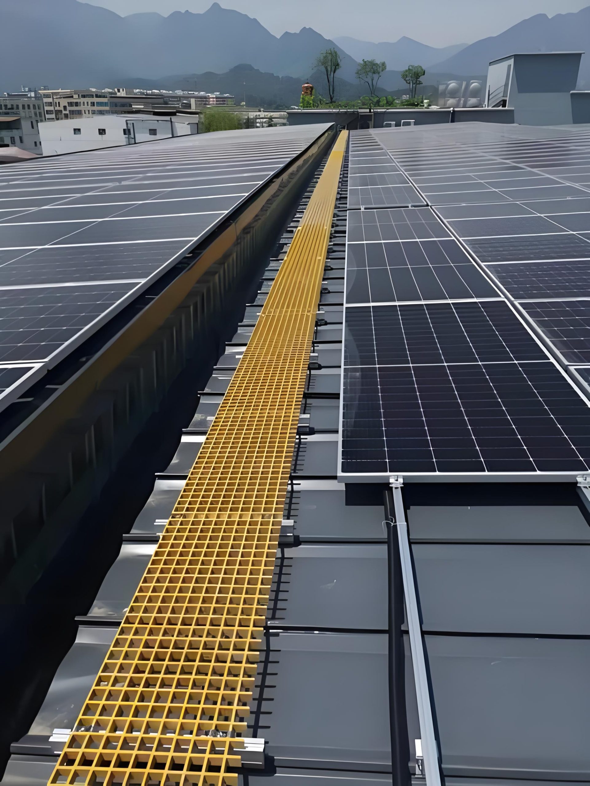
HDG grating panels form defined maintenance corridors between or alongside solar module rows. The open surface provides drainage and reduces debris accumulation while giving technicians stable access for module inspection, cleaning, connector checks, and replacement work.
Inverter Equipment Access
Walkways installed around inverters, transformers, combiner boxes, and control cabinets provide access for testing and scheduled maintenance. Panels can be fabricated around equipment bases, conduits, and structural members according to the electrical area layout.
Elevated Service Platforms
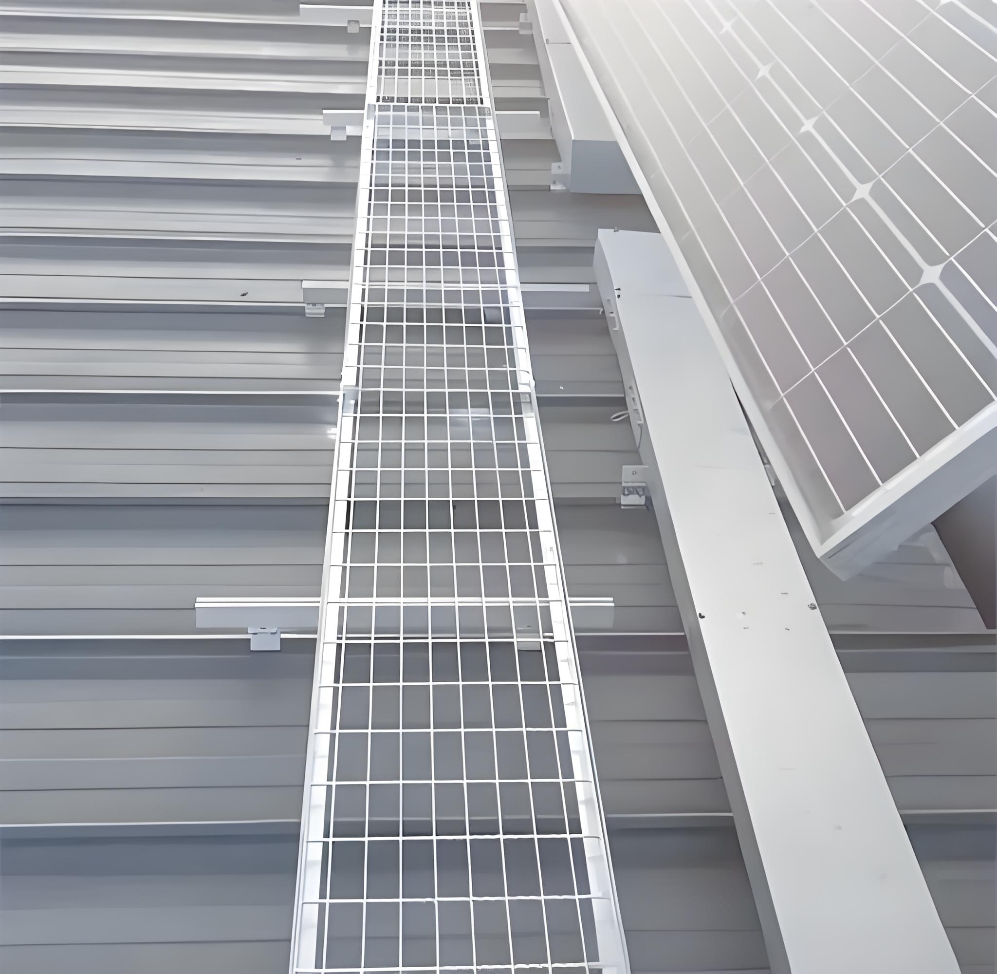
Galvanized grating is used on elevated platforms serving rooftop PV systems or raised equipment. Correctly oriented bearing bars transfer pedestrian and maintenance loads to the supporting steelwork, while securely fixed panels help prevent movement during service operations.
Cable Trench Crossings
Removable grating panels can provide walking access over cable trenches and designated service routes. The layout should maintain required access to cables, drainage channels, and inspection points without obstructing ventilation or routine electrical maintenance.
03 / SPECIFICATIONS & PRODUCT OPTIONS
Common Specifications & Available Options
Compare materials, bearing bar sizes, spacing, surface types, finishes and panel dimensions to match the requirements of the application.
Specifications
| Parameter | Specification / Options |
|---|---|
| Material | Carbon steel, commonly Q235B or ASTM A36, as specified by the project. |
| Surface treatment |
Hot-dip galvanized after fabrication. Coating requirements should follow the applicable project standard and service environment. |
| Bearing bar size |
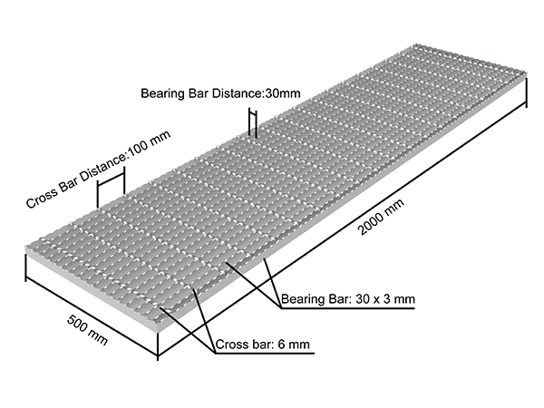
25 × 3 mm, 30 × 3 mm, 30 × 5 mm, 32 × 5 mm, or 40 × 5 mm. Final size depends on support span, design load, and deflection limits. |
| Bearing bar spacing |
30 mm or 40 mm. Centre to centre. |
| Cross bar spacing |
50 mm or 100 mm. Centre to centre. |
| Panel size examples |
1000 × 1000 mm, 1000 × 1200 mm, or 1000 × 3000 mm. Finished dimensions can be adjusted to the approved walkway layout. |
| Walking surface |
Plain or serrated bearing bars. Serrated grating may be specified where improved slip resistance is required. |
| Edge treatment | Welded banding bars around panel edges, openings, and site-specific cut-outs. |
| Fixing | Galvanized grating clips, saddle clips, or project-specified fixing assemblies compatible with the supporting steelwork. |
| Bearing direction |
Bearing bars must span between the designated structural supports. Direction should be clearly identified on layout and fabrication drawings. |
| Custom fabrication | Panels, notches, openings, toe plates, and removable sections can be manufactured according to approved drawings and PV equipment layouts. |
Need a different size? Send your layout for a custom panel review.
Request Your SpecificationThe sizes above are reference examples, not approved combinations for every span. Confirm the bearing direction, loads, clear span and material before ordering. Panel size does not indicate the allowable unsupported span.
WHY USE STEEL GRATING?
Advantages for Steel Grating Applications
Galvanized Corrosion Protection
Hot-dip galvanizing after fabrication protects carbon steel walkways against moisture and outdoor corrosion, including exposed edges and welded areas. This treatment is suited to the long-term environmental exposure found in solar farms and photovoltaic power plants.
Effective Rainwater Drainage
The open grid allows rainwater to pass through the walking surface instead of forming large pools on the maintenance route. This helps reduce water retention around PV support structures and keeps access areas easier to inspect after wet weather.
Ventilation and Light Passage
The open grating arrangement permits air movement and light transmission beneath the walkway. It can therefore be installed above cable routes or near equipment without creating a solid barrier that restricts ventilation or requires additional drainage provisions.
Configurable Slip Resistance
Plain and serrated bearing bar surfaces are available for different site conditions. Serrated bars can improve footing on wet or dusty service routes, while the final choice can be matched to the project safety assessment and maintenance requirements.
Drawing-Based Panel Fabrication
Panels can be cut and banded to suit solar array corridors, inverter bases, cable trenches, columns, and access openings. Manufacturing from approved drawings reduces field modification and helps maintain the intended bearing direction and support arrangement.
Replaceable Access Sections
Individual grating panels can be removed when cables, connectors, or electrical equipment require service. A sectional layout allows localized replacement or inspection without dismantling the entire PV maintenance walkway.
04 / INSTALLATION & PROJECT PHOTOS
Installation Guidance & Application Photos
Review the panel layout, support conditions, fixing methods and fabrication details before installation, and refer to the application photos for practical examples.
-
Verify Supports and Drawings
Confirm the supporting steel dimensions, elevations, panel references, access clearances, and approved walkway layout before installation. Check that each support span matches the grating design and that equipment, cables, and drainage paths remain unobstructed.
-
Position the Panels
Place each panel in its scheduled location with the bearing bars spanning between structural supports. Maintain the specified bearing length, joint clearance, and alignment, and check that banded edges and equipment cut-outs fit without forcing the panel.
-
Install the Fixings
Secure the grating with the specified clips or fixing assemblies at the required locations. Avoid unnecessary site cutting or welding that could damage the galvanized coating. Treat any approved cut or damaged area with a suitable zinc-rich repair system.
-
Complete the Inspection
Check every panel for rocking, displacement, sharp edges, missing clips, and coating damage. Confirm that walkway openings remain clear and establish periodic inspections for loose fixings, corrosion, debris accumulation, and damage caused by maintenance activities.
05 / RELATED REFERENCE & FAQ
Frequently Asked Questions
Why is hot-dip galvanized grating used for photovoltaic power plant walkways?
Photovoltaic facilities are continuously exposed to rain, humidity, temperature changes, and airborne contaminants. Hot-dip galvanizing coats the fabricated carbon steel, including many edges and welded areas, to provide long-term corrosion protection. The open grating surface also drains water, limits debris accumulation, and allows air and light to pass through maintenance routes.
What bearing bar size is suitable for a PV maintenance walkway?
The required bearing bar size depends on the clear support span, pedestrian and maintenance loads, allowable deflection, and applicable project standard. Common options include 30 × 3 mm, 30 × 5 mm, and 40 × 5 mm. The final selection should be verified from structural calculations rather than chosen only from a standard panel schedule.
Should a photovoltaic walkway use plain or serrated grating?
Plain grating is suitable for many normally drained maintenance routes. Serrated bearing bars may be preferred where walkways are frequently wet, dusty, inclined, or exposed to residues that increase slipping risk. Surface selection should follow the project safety assessment, operating conditions, footwear requirements, and local regulations; serrations do not replace proper drainage or housekeeping.
Can grating panels be customized around solar equipment and cables?
Yes. Panels can be fabricated with banded openings, notches, removable sections, and dimensions matched to inverters, cable trays, conduits, columns, and equipment bases. Approved layout drawings should identify all cut-outs and panel references before production. Factory fabrication is preferred because it provides controlled dimensions and allows galvanizing to be completed after cutting and welding.
How should HDG grating walkways be fixed to PV support structures?
Panels are normally secured with galvanized grating clips or project-specific fixing assemblies compatible with the supporting steel. Fixing quantity and location depend on panel size, wind exposure, vibration, access requirements, and the structural design. Clips should prevent uplift and movement without obstructing removable areas, and their condition should be checked during scheduled maintenance.
How should cut or damaged galvanized surfaces be treated on site?
Site cutting should be minimized and performed only where approved by the project engineer. Exposed steel and damaged coating areas must be cleaned and repaired with an appropriate zinc-rich coating or another method permitted by the governing galvanizing standard and project specification. Repaired areas should be inspected before the walkway is placed into service.
06 / PROJECT ENQUIRY
Tell Us About Your Walkway
Share your layout and operating requirements so our team can review the grating, fabrication and supply scope.
Send Drawings by Email Discuss on WhatsAppThe email button opens your mail app. Attach your drawings before sending.
Include these details
- Application location and exposure conditions
- Drawings, panel dimensions and quantities
- Support layout, clear span and design loads
- Material, finish and walking-surface requirements
- Cut-outs, fixings and removable access sections
- Destination, required delivery date and project standards
Already have a specification? Send it with your enquiry.