

01 / APPLICATION OVERVIEW
Height-Adjustable Steel Grating Stairs for Strong, Durable Access
Height-adjustable steel grating stairs provide secure access to raised equipment and platforms, with a mechanically adjustable support arrangement for setting the required installation height.
These assemblies combine grating treads, supporting stringers, adjustable legs or brackets, and project-specified handrails. They suit installations where access levels vary between equipment configurations or require adjustment during commissioning. The adjustment mechanism must hold the stair securely at its approved operating position.
Selection should consider minimum and maximum access height, available floor space, tread geometry, design loads, and support conditions. Adjustment range, locking details, foundation bearing, corrosion protection, and handrail alignment must be checked together so the stairs remain stable and usable throughout their permitted settings.
Discuss Your Walkway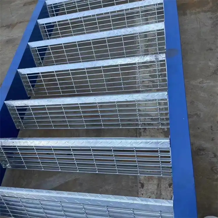
02 / APPLICATION SCENARIOS & REQUIREMENTS
Application Scenarios & Project Requirements
Review the operating conditions, users, loads, environment and project requirements before selecting the appropriate steel grating specification.
Production Equipment Access
Adjustable stairs provide access to raised operating positions beside production equipment. The installation height can be set to match the equipment configuration, while tread positions, landing clearance, and handrails are coordinated with the operator’s working area.
Modular Service Platforms
Stairs can connect floor level to modular maintenance platforms installed at different elevations. Approved adjustment details allow the assembly to be configured for the required platform height without relying on loose packing beneath the stair supports.
Processing and Packaging Lines
Grating stair assemblies provide personnel access beside conveyors, packaging machines, and process skids. Height adjustment can accommodate planned line configurations, provided the stair remains clear of moving components and preserves the required operating and maintenance spaces.
Outdoor Utility Access
Galvanized stairs provide access to elevated utility equipment and service decks exposed to rainfall. Designed leveling provisions can accommodate installation tolerances, with each support seated on a suitable foundation and locked before the stairs enter service.
03 / SPECIFICATIONS & PRODUCT OPTIONS
Common Specifications & Available Options
Compare materials, bearing bar sizes, spacing, surface types, finishes and panel dimensions to match the requirements of the application.
Specifications
| Parameter | Specification / Options |
|---|---|
| Material |
Carbon steel grating treads, stringers, support legs, mounting brackets, and landing frames to the project-specified structural grade. Specify compatible materials for adjustment screws, pins, fasteners, and replaceable bearing components. |
| Surface treatment |
Hot-dip galvanized after fabrication for suitable outdoor or humid environments; a project-specified paint system may be used for indoor installations. Account for coating thickness at threaded, sliding, and pinned connections so adjustment remains possible after finishing. |
| Tread bearing bar size |
Common grating sections include 25 × 3, 30 × 3, 30 × 5, 32 × 5, and 40 × 5 mm. Bar height × thickness. Select for the clear span between tread supports, concentrated loads, surface profile, and allowable deflection. |
| Grating spacing |
Common bearing bar pitches: 30 or 40 mm. Common cross bar pitches: 50 or 100 mm. Typical combinations include 30 × 50, 30 × 100, 40 × 50, and 40 × 100 mm. Dimensions are center-to-center. A 30 mm pitch with 3 mm thick bearing bars gives a 27 mm clear gap; verify openings for the intended users. |
| Tread dimensions |
Fabrication examples include 600 × 250, 800 × 250, 800 × 280, 900 × 280, and 1,000 × 300 mm. Tread width × overall depth. Confirm clear access width and effective going separately; nosing and tread overlap affect the usable geometry. |
| Access height and rise |
Example target platform levels include 450, 600, 750, 900, and 1,200 mm. At a nominal 150 mm rise, these correspond to 3, 4, 5, 6, and 8 equal rises respectively. These are layout examples, not adjustment ranges or universal stair limits. The upper platform may form the final stepping surface, so tread quantity is determined separately. |
| Height adjustment |
Engineered threaded feet, telescopic supports, or adjustable mounting brackets, depending on the selected stair system. State minimum height, maximum height, usable travel, and any pin increments in millimeters. Installation leveling and substantial access-height adjustment require different design provisions. |
| Top landing dimensions |
Illustrative landing modules include 800 × 800, 1,000 × 1,000, and 1,200 × 1,000 mm. Clear width × travel depth. Determine the actual landing size from stair width, equipment access, door movement, and the applicable access requirements. |
| Tread surface and edges |
Plain or serrated grating with project-specified nosing. Matching banding examples include 25 × 3, 30 × 5, and 40 × 5 mm. Banding height × thickness. Detail the leading edge, end plates, and nosing projection on the tread drawing; edge banding is not automatically a structural support. |
| Bearing direction and support |
Tread bearing bars span between the designed side supports. Stringers, adjustable legs, base plates, and anchors are sized for every permitted operating height. Check support extension, screw or sleeve engagement, bracing, and foundation bearing at the maximum adjustment position. |
| Locking and handrails |
Designed locking nuts, retained pins, bolted restraints, or other positive locking provisions, with handrails and guards coordinated to the adjustment system. Specify fastener sizes, tightening requirements, rail heights, and clear openings on approved drawings. Handrails must remain effective after adjustment. |
Need a different size? Send your layout for a custom panel review.
Request Your SpecificationThe sizes above are reference examples, not approved combinations for every span. Confirm the bearing direction, loads, clear span and material before ordering. Panel size does not indicate the allowable unsupported span.
WHY USE STEEL GRATING?
Advantages for Steel Grating Applications
Adjustable Installation Height
Designed adjustment provisions allow the stair to match an approved platform elevation or installation tolerance. The available range is defined together with the tread geometry, supports, and locking arrangement.
Verified Structural Support
Steel treads, stringers, and adjustable supports can be sized for specified personnel and maintenance loads. Verification at the permitted adjustment positions accounts for changes in support extension and connection forces.
Open Tread Drainage
Grating openings allow rainwater and wash water to pass through the treads, reducing surface pooling. The area beneath the stairs should receive this water without affecting equipment or adjacent access routes.
Traction Surface Options
Serrated bearing bars and suitable nosing provide additional contact edges for footwear. Their selection should reflect moisture, contamination, and cleaning practices, while maintaining the required tread dimensions and structural capacity.
Exposure-Matched Protection
Galvanizing or an appropriate coating system protects fabricated steel for the intended environment. Accessible adjustment components can be inspected and maintained to limit corrosion that could prevent movement or weaken connections.
Serviceable Components
Bolted treads and replaceable adjustment components can simplify planned repairs where the design provides for removal. Identified parts and documented settings help maintenance teams restore the approved stair configuration.
04 / INSTALLATION & PROJECT PHOTOS
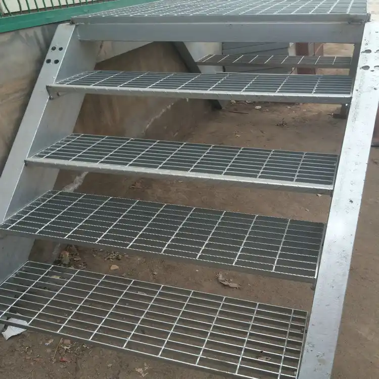
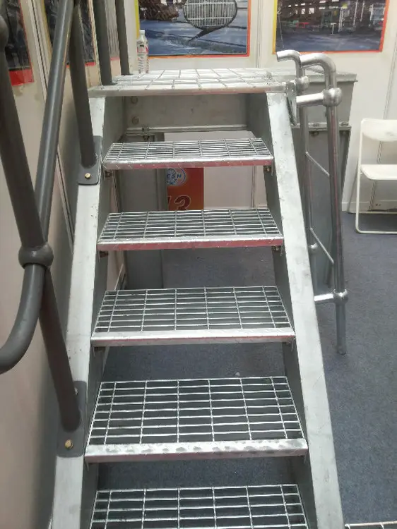
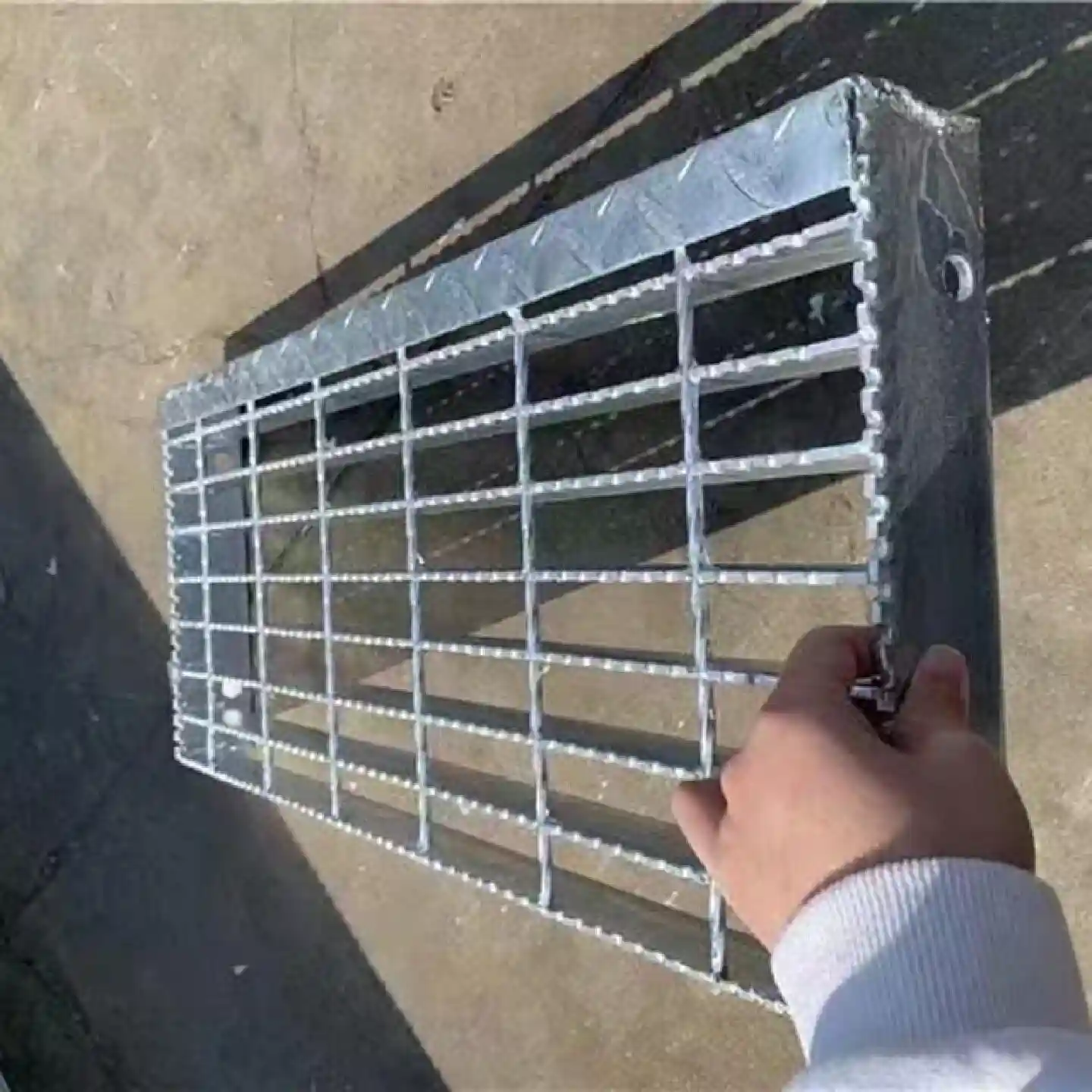
Installation Guidance & Application Photos
Review the panel layout, support conditions, fixing methods and fabrication details before installation, and refer to the application photos for practical examples.
-
Verify Heights and Foundations
Measure the finished lower floor and upper access level, available horizontal run, and landing clearances. Confirm that the required setting falls within the approved adjustment range and that foundations, anchors, and supporting surfaces match the installation drawings.
-
Position and Adjust the Assembly
Position the stairs using suitable lifting equipment and temporary support. Keep the assembly unloaded while adjusting the designed feet, legs, or brackets. Maintain the specified thread engagement or support overlap, and check that treads and landings remain level.
-
Lock Supports and Complete Connections
Engage all specified locking nuts, pins, retainers, and structural connections. Complete anchors, tread fixings, handrails, and guards in the approved sequence. Verify uniform rise, effective going, and the transitions at both ends before removing temporary support.
-
Inspect and Record the Setting
Check stability, footing contact, fastener security, headroom, rail alignment, and protective finishes. Record the operating height and complete the specified acceptance checks. Reinspect the entire stair whenever its height or installation position changes.
05 / RELATED REFERENCE & FAQ
Frequently Asked Questions
How much height adjustment can a steel grating stair provide?
The range depends on the specific support and stair mechanism. Threaded leveling feet may accommodate installation tolerances, while a system designed for larger height changes requires coordinated tread and support geometry. Specify the minimum and maximum finished access heights before manufacture rather than assuming one adjustment range applies to every assembly.
Does changing the support height keep all stair rises equal?
Not automatically. Raising a rigid stair can change the first or last rise without changing the intermediate rises. Altering the stair angle can also affect tread level and going. The approved adjustment system must address these relationships, and each operating setting requires a geometry check before use.
Which tread dimensions and bar sizes are commonly considered?
Example tread sizes include 600 × 250, 800 × 280, and 1,000 × 300 mm. Common grating sections include 25 × 3, 30 × 3, 30 × 5, and 40 × 5 mm. These are fabrication options; the final selection depends on tread span, required access width, loads, and the approved stair geometry.
Can the stairs be adjusted while someone is standing on them?
Mechanically set-height access stairs should be unloaded and taken out of service before adjustment, following the approved procedure. Support the assembly, change the setting, and engage every restraint before inspection. A stair intended to move while occupied requires a separately engineered system and should not be assumed equivalent to an adjustable fixed-access stair.
Are adjustable grating stairs suitable for outdoor installations?
They can be when the structure, finish, foundations, and adjustment components are specified for outdoor conditions. Galvanizing may suit the steelwork, while threads and sliding interfaces need appropriate detailing and maintenance. Inspect for corrosion, seized adjusters, loose restraints, and contaminants that affect footing or drainage.
What information is needed to quote height-adjustable grating stairs?
Provide minimum and maximum access heights, normal operating height, available floor footprint, required width, and landing details. Include design loads, adjustment frequency, support conditions, preferred tread surface, and corrosion exposure. Identify whether adjustment is only for installation leveling or for planned changes between operating configurations.
06 / PROJECT ENQUIRY
Tell Us About Your Walkway
Share your layout and operating requirements so our team can review the grating, fabrication and supply scope.
Send Drawings by Email Discuss on WhatsAppThe email button opens your mail app. Attach your drawings before sending.
Include these details
- Application location and exposure conditions
- Drawings, panel dimensions and quantities
- Support layout, clear span and design loads
- Material, finish and walking-surface requirements
- Cut-outs, fixings and removable access sections
- Destination, required delivery date and project standards
Already have a specification? Send it with your enquiry.