

01 / APPLICATION OVERVIEW
Hot-Dip Galvanized Steel Grating for Transformer Bays
Hot-dip galvanized steel grating provides durable maintenance access and removable pit covers for transformer bays exposed to rain and outdoor operating conditions.
Grating panels can form inspection routes beside transformers, access platforms near auxiliary equipment, and covers over designated collection pits or service trenches. Panel layouts should accommodate maintenance activities, cable entries, structural supports, and the bay’s oil containment arrangement.
Selection should consider personnel and maintenance loads, support span, bearing direction, electrical clearances, corrosion exposure, and panel removal requirements. Coordinate grating supports, bonding provisions, drainage, oil containment, and fire protection with the approved transformer bay design.
Discuss Your Walkway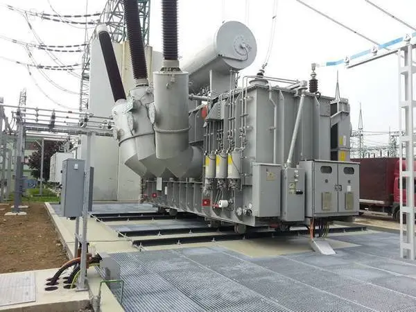
02 / APPLICATION SCENARIOS & REQUIREMENTS
Application Scenarios & Project Requirements
Review the operating conditions, users, loads, environment and project requirements before selecting the appropriate steel grating specification.
Transformer Inspection Walkways
Grating walkways provide defined routes for checking transformer condition, reading accessible instruments, and inspecting external fittings. Their position should maintain the required electrical clearances and allow personnel to work without stepping onto pipes, cable supports, or containment surfaces.
Oil Collection Pit Covers
Removable grating panels can cover designated oil collection pits where the engineered containment design permits an open surface. Supports and openings must coordinate with the specified drainage and fire protection arrangement, while allowing inspection and removal of accumulated debris.
Auxiliary Equipment Platforms
Grating platforms provide access beside cooling equipment, control cabinets, and other transformer auxiliaries. Panel dimensions and support locations should preserve equipment service clearances and accommodate concentrated maintenance loads where tools or replacement components will be placed.
Service Trench Access
Grating covers can provide removable access over trenches designed for open covers within transformer installations. Use depends on cable protection, water ingress, electrical separation, and fire requirements; trenches requiring sealed or fire-rated covers need the specified alternative construction.
03 / SPECIFICATIONS & PRODUCT OPTIONS
Common Specifications & Available Options
Compare materials, bearing bar sizes, spacing, surface types, finishes and panel dimensions to match the requirements of the application.
Specifications
| Parameter | Specification / Options |
|---|---|
| Material | Carbon steel bearing bars, cross bars, and perimeter banding to the project-specified structural grades. |
| Surface treatment |
Hot-dip galvanized after fabrication to the specified standard, such as ISO 1461 or ASTM A123/A123M where applicable. Specify coating acceptance requirements and approved repair methods for installation damage. |
| Bearing bar size |
Common examples include 25 × 3, 30 × 3, 30 × 5, 32 × 5, and 40 × 5 mm. Height × thickness; verify the section for actual loads, clear span, and allowable deflection. |
| Bearing bar spacing |
Typical center-to-center spacing: 30 or 40 mm, with closer spacing where required for access or object-retention criteria. Confirm clear openings separately from bar pitch. |
| Cross bar spacing | Typical center-to-center spacing: 50 or 100 mm, subject to the selected grating construction and project requirements. |
| Panel dimensions |
Cut-to-size panels manufactured to approved transformer bay layouts, pit dimensions, and support drawings. Coordinate panel weight and removal direction with available lifting space and electrical clearances. |
| Walking surface |
Plain or serrated bearing bars selected through the site slip-risk assessment. Serrations do not eliminate slip hazards from transformer oil or other contamination. |
| Edge treatment | Banded edges, framed cut-outs, and toe plates where specified, with additional supports around openings as required. |
| Bearing direction |
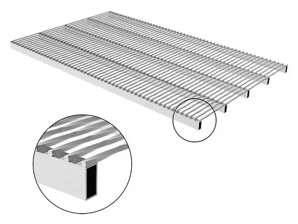
Bearing bars span between designated structural supports with the specified end bearing. Show the load-bearing direction and supported edges on every panel drawing. |
| Fixing | Galvanized or otherwise compatible hold-down clips and bolted restraints selected for support geometry and maintenance access. |
| Electrical bonding provisions |
Connection points and bonding arrangements provided according to the substation earthing design. Ordinary grating clips should not be assumed to provide verified electrical continuity. |
Need a different size? Send your layout for a custom panel review.
Request Your SpecificationThe sizes above are reference examples, not approved combinations for every span. Confirm the bearing direction, loads, clear span and material before ordering. Panel size does not indicate the allowable unsupported span.
WHY USE STEEL GRATING?
Advantages for Steel Grating Applications
Outdoor Corrosion Protection
Galvanizing after fabrication protects exposed steel surfaces, welded joints, and cut edges. The coating supports outdoor service in transformer bays when selected for the local atmosphere and maintained where damaged.
Surface Water Drainage
Open grating allows rainfall to pass through the walking surface, reducing pooling along inspection routes. Water and any oil contamination must enter the collection system specified for the transformer bay.
Engineered Maintenance Access
Bearing bar sections and supports can be selected for personnel, tools, and defined maintenance loads. This provides a load-verified access surface around equipment and across designated pit openings.
Removable Inspection Panels
Mechanically secured panels can be removed for pit inspection, cleaning, and access to concealed services. Panel sizes and lifting provisions can be coordinated with the permitted maintenance procedure.
Fit Around Bay Equipment
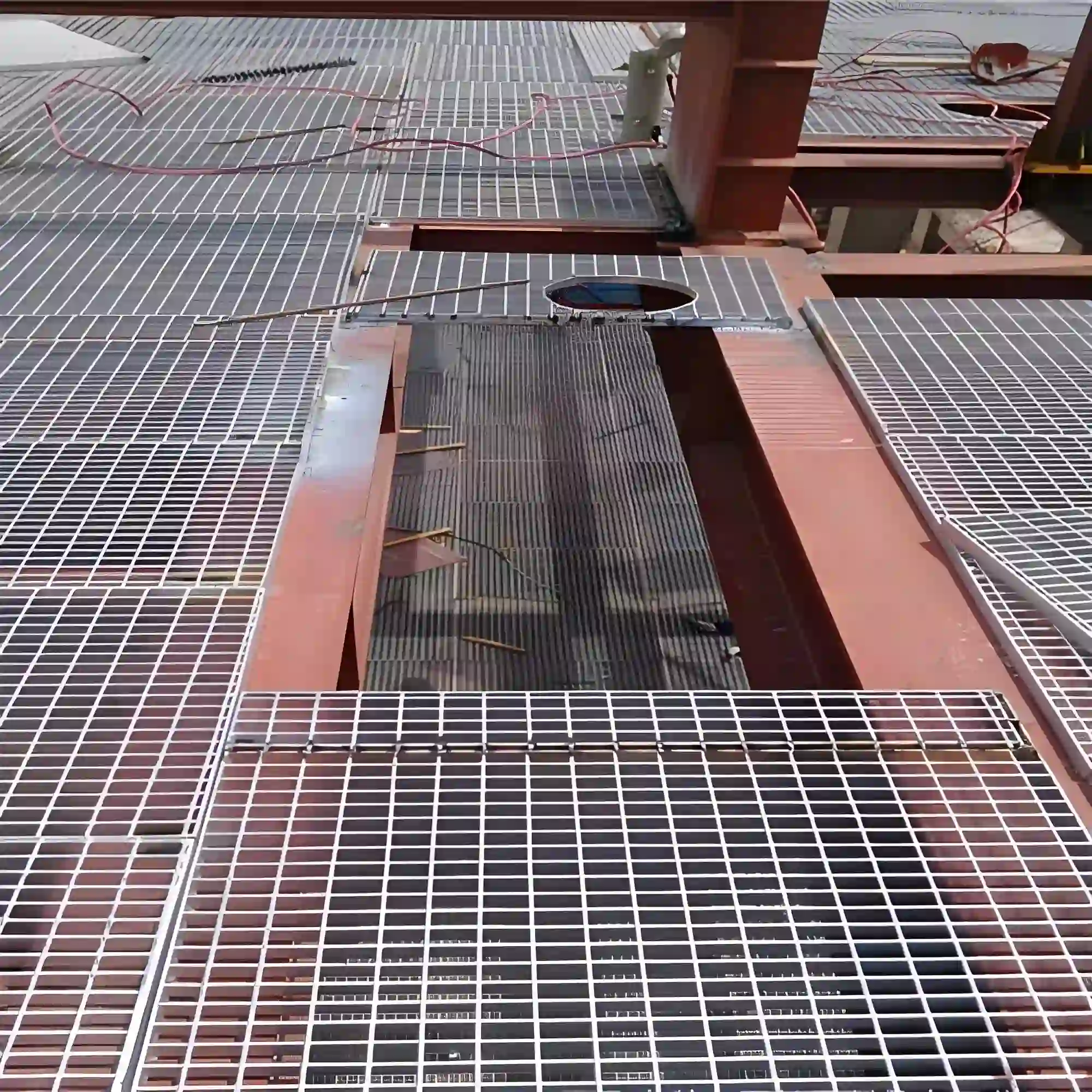
Factory-fabricated panels can accommodate foundations, support columns, pipes, and designated cable entries. Planned cut-outs and local supports help preserve load capacity while reducing adjustments near installed electrical equipment.
Visibility Below the Surface
The open grid allows observation of accessible areas beneath the panels, helping personnel identify debris or standing liquid during inspections. Detailed checks and cleaning remain possible through designated removable sections.
04 / INSTALLATION & PROJECT PHOTOS
Installation Guidance & Application Photos
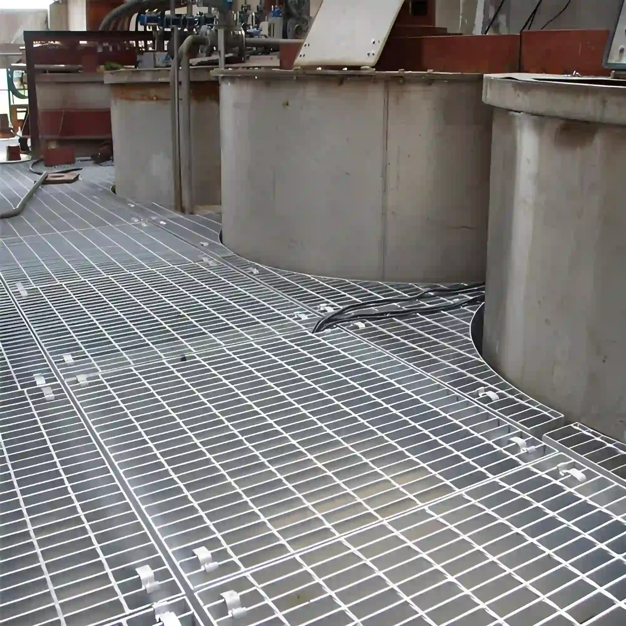
Review the panel layout, support conditions, fixing methods and fabrication details before installation, and refer to the application photos for practical examples.
-
Verify Bay Readiness
Confirm the approved work authorization and electrical isolation or clearance arrangements. Check support locations, pit dimensions, elevations, design loads, and containment interfaces against the drawings before bringing grating panels into the installation area.
-
Position the Grating Panels
Match panel identification to the bay layout and verify bearing direction, end bearing, and removal clearances. Use the approved handling method and maintain electrical clearances throughout lifting. Do not cut bearing bars or enlarge equipment openings without approved details.
-
Secure and Bond as Specified
Install the specified restraints at the designated supports. Complete bonding connections according to the earthing drawings, including provisions for removable panels where required. Keep fasteners and bonding conductors clear of drainage paths and equipment service spaces.
-
Inspect Before Handover
Check panel stability, joints, fasteners, edge clearances, and coating condition. Remove installation debris, confirm access to collection outlets, and complete the specified bonding verification. Repair coating damage and confirm that containment and fire protection components remain correctly installed.
05 / RELATED REFERENCE & FAQ
Frequently Asked Questions
Why is hot-dip galvanized grating used in transformer bays?
It combines a structural walking surface with zinc protection for outdoor exposure. Openings allow rainfall to pass into the designated drainage or containment system, and removable panels provide maintenance access. Suitability depends on the bay’s loading, electrical clearances, environmental conditions, and approved containment design.
Can steel grating cover a transformer oil collection pit?
Yes, where the engineered pit design specifies an open grating cover. The panels and supports must carry the required loads and preserve the intended liquid flow path. Ordinary grating does not provide oil containment or replace specified fire-control measures, such as stone layers or purpose-designed fire suppression assemblies.
Do galvanized grating panels require electrical bonding?
Bonding requirements are determined by the substation earthing design and applicable electrical rules. Where bonding is required, provide the specified connections and verify continuity. Galvanizing does not make steel electrically insulating, and ordinary clips or contact with supporting steel should not be assumed to provide an adequate bonding connection.
How is the bearing bar size selected for transformer bay access?
Use the specified distributed and concentrated loads, support span, bar spacing, and deflection limits. Include tools or maintenance equipment that may be placed on the panels. Pedestrian grating should not be assumed suitable for transformer transport, jacking, or heavy component handling without separate structural verification.
Should transformer bay grating have a serrated surface?
Serrated bars may be appropriate for routes exposed to rain or other wet conditions, subject to the site assessment. They do not make an oil-contaminated surface safe to walk on. Surface selection should be combined with leak management, prompt cleaning, suitable footwear, and inspection procedures.
What drawings and specifications are needed before fabrication?
Provide the bay layout, support locations, panel dimensions, design loads, bearing direction, cut-outs, and galvanizing requirements. Include restraint details, bonding provisions, lifting arrangements, and electrical clearances. Identify drainage, oil containment, and fire protection interfaces so fabrication and panel removal can be coordinated with the complete installation.
06 / PROJECT ENQUIRY
Tell Us About Your Walkway
Share your layout and operating requirements so our team can review the grating, fabrication and supply scope.
Send Drawings by Email Discuss on WhatsAppThe email button opens your mail app. Attach your drawings before sending.
Include these details
- Application location and exposure conditions
- Drawings, panel dimensions and quantities
- Support layout, clear span and design loads
- Material, finish and walking-surface requirements
- Cut-outs, fixings and removable access sections
- Destination, required delivery date and project standards
Already have a specification? Send it with your enquiry.