

01 / APPLICATION OVERVIEW
Offshore Platform Grating – Corrosion & Slip Resistance
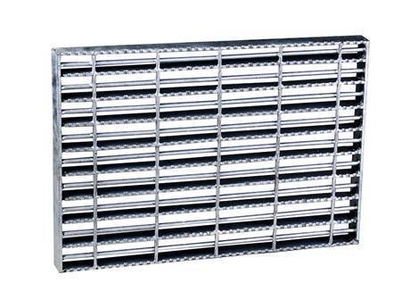
Offshore platform grating provides load-bearing access across exposed decks and equipment areas, with corrosion protection and walking surfaces selected for marine operating conditions.
Grating panels form inspection walkways, operating platforms, stair landings, and removable covers around offshore equipment. The open grid allows water to pass through where the deck design permits, while planned panel sections provide access to supporting steelwork and services below.
Selection should consider salt spray, repeated wetting, process contamination, design loads, support span, and bearing direction. Surface profile, panel restraints, coating compatibility, dropped-object requirements, drainage collection, and maintenance access must be coordinated with the platform specification.
Discuss Your Walkway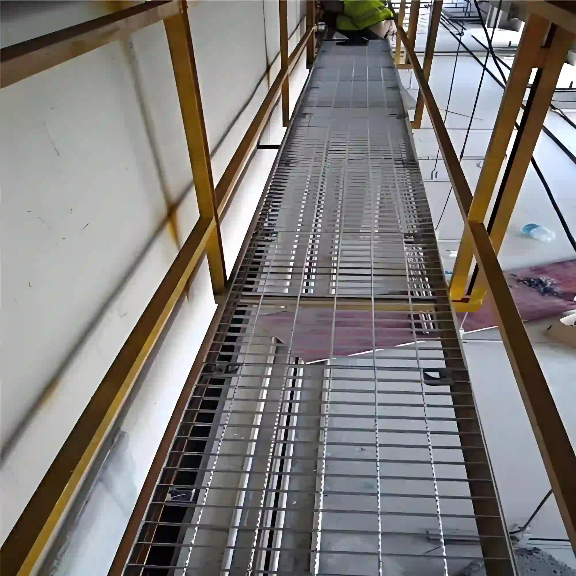
02 / APPLICATION SCENARIOS & REQUIREMENTS
Application Scenarios & Project Requirements
Review the operating conditions, users, loads, environment and project requirements before selecting the appropriate steel grating specification.
Exposed Deck Walkways
Grating provides defined walking routes across external platform areas exposed to rainfall and salt spray. Surface selection should reflect footwear and expected contamination, while panel supports and restraints must accommodate the specified environmental and operational loads.
Process Equipment Platforms
Platforms around vessels, pumps, and valve groups provide standing space for operation and inspection. Panels can include supported openings for pipe penetrations, with sufficient clearance for insulation, thermal movement, and access to equipment fittings.
Utility and Washdown Areas
Grating floors serve utility areas where rainwater or wash water frequently wets the walking surface. The protective system must suit cleaning agents and other contaminants, and liquids passing through require an appropriate drainage or collection arrangement below.
Removable Service Covers
Mechanically secured panels provide access above service openings and designated pits. Panel weight, lifting provisions, and restraints should support controlled removal and reinstatement, with suitable protection for personnel and equipment on lower levels.
03 / SPECIFICATIONS & PRODUCT OPTIONS
Common Specifications & Available Options
Compare materials, bearing bar sizes, spacing, surface types, finishes and panel dimensions to match the requirements of the application.
Specifications
| Parameter | Specification / Options |
|---|---|
| Material |
Carbon steel bearing bars, cross bars, and perimeter members to the project-specified structural grade. Specify material traceability and toughness requirements where applicable. Stainless steel alternatives require separate assessment of grade, exposure, and connection compatibility. |
| Corrosion protection |
Hot-dip galvanized after fabrication where suitable; galvanizing with a compatible additional coating may be specified for more demanding marine exposure. Define the coating standard, preparation, thickness, acceptance criteria, and repair system for actual salt spray, chemical contact, and wetting conditions. |
| Bearing bar size |
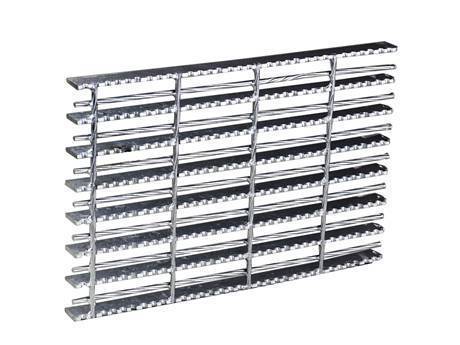
Common starting sections include 30 × 5, 32 × 5, 40 × 5, and 50 × 5 mm. Heavier options such as 50 × 6, 60 × 6, or 75 × 6 mm may be considered where calculations require them. Bar height × thickness. Select for actual loads, clear span, allowable deflection, and the specified plain or serrated profile. |
| Bearing bar spacing |
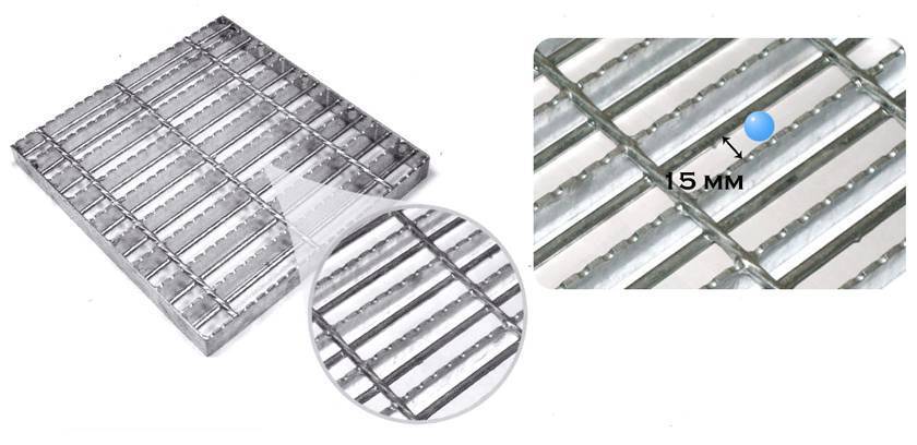
Common center-to-center pitches include 20, 30, and 40 mm, subject to the selected manufacturing system. With 5 mm thick bars, these give clear gaps of 15, 25, and 35 mm respectively. Confirm opening limits for footwear, tools, and activities below. |
| Cross bar spacing |
Common center-to-center pitches include 50 and 100 mm, giving grid combinations such as 20 × 50, 30 × 50, 30 × 100, and 40 × 100 mm. Bearing bar pitch × cross bar pitch. Assess clear openings in both directions rather than relying on bearing bar spacing alone. |
| Panel size examples |
Indicative fabrication modules include 600 × 1,000, 800 × 1,000, 1,000 × 1,000, and 1,200 × 1,000 mm. Bearing bar length × panel width. Final dimensions follow support locations, access width, lifting limits, and approved deck drawings; these examples are not span ratings. |
| Walking surface |
Plain, serrated, or another project-approved traction profile selected for expected wetting, contaminants, and footwear. Define the profile and request relevant slip-performance evidence where required. Use structural load data applicable to the selected surface. |
| Banding and toe plates |
Banding examples include 30 × 5, 40 × 5, and 50 × 5 mm to match the bearing bar depth. Toe plate examples include 100 × 5 and 150 × 5 mm. Height × thickness. Confirm the required toe plate projection above the deck and provide engineered support around interrupted bearing bars. |
| Bearing direction and support |
Bearing bars span between designated deck beams with the specified end bearing and support conditions. Dimension clear spans and supported edges on drawings. Ordinary cross bars and perimeter banding should not be assumed to replace structural supports. |
| Panel restraints |
Engineered hold-down clips, bolted restraints, or approved welded connections. M8 and M10 clip-bolt assemblies are common starting options where compatible with the selected system. Verify connection capacity, quantity, locking provisions, support engagement, and corrosion compatibility for vibration and applicable uplift or displacement loads. |
| Loads and custom fabrication |
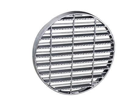
Specify distributed loads, concentrated loads, contact areas, and relevant dynamic actions. Include framed penetrations, removable modules, lifting provisions, and permanent panel identification. Coordinate dropped-object controls, bonding provisions, and required inspection or certification documents with the offshore project specification. |
Need a different size? Send your layout for a custom panel review.
Request Your SpecificationThe sizes above are reference examples, not approved combinations for every span. Confirm the bearing direction, loads, clear span and material before ordering. Panel size does not indicate the allowable unsupported span.
WHY USE STEEL GRATING?
Advantages for Steel Grating Applications
Marine Exposure Protection
Galvanizing and compatible coating systems can protect fabricated carbon steel against specified marine conditions. Selecting the system for actual exposure helps establish realistic inspection, repair, and replacement requirements.
Traction Surface Options
Serrated or other approved profiles provide additional contact features for footwear. Surface selection can address expected wetting and contamination, supported by relevant performance evidence and routine removal of oil or process deposits.
Reduced Surface Pooling
Openings allow rainwater and wash water to leave the walking surface. The deck arrangement below can direct discharge toward approved collection points and protect equipment or occupied areas from falling liquids.
Verified Operating Strength
Bearing bars and supports can be sized for defined personnel and maintenance loads. Checking strength, deflection, and connections together provides a verified access surface rather than relying on nominal bar dimensions alone.
Replaceable Deck Modules
Mechanically restrained panels can be removed individually for inspection or replacement. Identified modules and coordinated lifting provisions help maintenance teams access underlying services and restore the approved deck layout.
Equipment-Specific Fabrication
Factory-prepared panel shapes and framed openings can accommodate piping, columns, and equipment interfaces. Coordinating these details preserves the intended load path and limits modifications in congested offshore work areas.
04 / INSTALLATION & PROJECT PHOTOS
Installation Guidance & Application Photos
Review the panel layout, support conditions, fixing methods and fabrication details before installation, and refer to the application photos for practical examples.
-
Verify Supports and Work Controls
Confirm the approved offshore work arrangements, lifting method, and protection around open deck areas. Check support positions, elevations, clear spans, corrosion condition, and specified loads against the installation drawings before placing panels.
-
Position Identified Panels
Match panel marks to the deck layout and verify bearing direction, end bearing, and equipment clearances. Control panels and loose components during handling. Provide approved support at penetrations and avoid unapproved cuts through bearing bars or frames.
-
Secure Restraints and Complete Edges
Install the specified hold-downs, locking components, and any required bonding connections. Complete toe plates and framed openings without blocking drainage. Follow approved tightening or welding procedures and restore finishes damaged during installation.
-
Inspect Before Operational Use
Check panel stability, restraint engagement, joints, exposed edges, and coating condition. Remove contaminants and verify drainage collection and dropped-object controls. Record acceptance checks and confirm that all access panels and fasteners are reinstated before reopening the deck.
05 / RELATED REFERENCE & FAQ
Frequently Asked Questions
Which corrosion protection is suitable for offshore platform grating?
Hot-dip galvanizing may suit some marine exposure conditions, while more demanding locations can require a compatible additional coating or another material system. Selection depends on salt deposition, wetting, chemical contact, temperature, and maintenance access. Specify the exposure and protective-system requirements before fabrication rather than assuming galvanizing suits every offshore location.
Does serrated grating remain slip-resistant when contaminated with oil?
Oil, grease, and process deposits can reduce traction even on serrated bars. Select the surface using expected contaminants, footwear, and any required slip assessment or testing. Drainage, leak control, and prompt cleaning remain necessary, especially where deposits fill the profile or obscure the walking surface.
Which bar sizes and grid dimensions are commonly considered?
Starting sections include 30 × 5, 32 × 5, 40 × 5, and 50 × 5 mm, with heavier bars considered where calculations require them. Common grids include 30 × 50 and 30 × 100 mm center-to-center. Final selection depends on loads, clear span, deflection, surface profile, and opening restrictions.
How should offshore grating panels be secured against movement?
Use restraints verified for the panel geometry, support arrangement, vibration, and applicable uplift or displacement loads. M8 or M10 clip bolts are connection options rather than proof of adequate capacity. Specify the complete clip system, locking method, fixing locations, and inspection requirements on approved drawings.
How are dropped-object risks managed with open grating?
Specify clear grid openings, panel joints, and perimeter gaps according to the project requirements and activities below. Toe plates, tool controls, framed penetrations, or supplementary barriers may also be needed. Any added mesh should be assessed for secure attachment, corrosion, drainage, and cleaning access as part of the complete assembly.
What information is needed to quote offshore platform grating?
Provide deck layouts, support locations, clear spans, loads, panel dimensions, and bearing direction. Include bar sections, grid pitches, surface profile, corrosion protection, and restraint details. Identify cut-outs, removable sections, dropped-object requirements, bonding provisions, and the material, inspection, or certification documents required by the project.
06 / PROJECT ENQUIRY
Tell Us About Your Walkway
Share your layout and operating requirements so our team can review the grating, fabrication and supply scope.
Send Drawings by Email Discuss on WhatsAppThe email button opens your mail app. Attach your drawings before sending.
Include these details
- Application location and exposure conditions
- Drawings, panel dimensions and quantities
- Support layout, clear span and design loads
- Material, finish and walking-surface requirements
- Cut-outs, fixings and removable access sections
- Destination, required delivery date and project standards
Already have a specification? Send it with your enquiry.