

01 / APPLICATION OVERVIEW
Steel Grating Facades for Ventilation, Daylight and Security
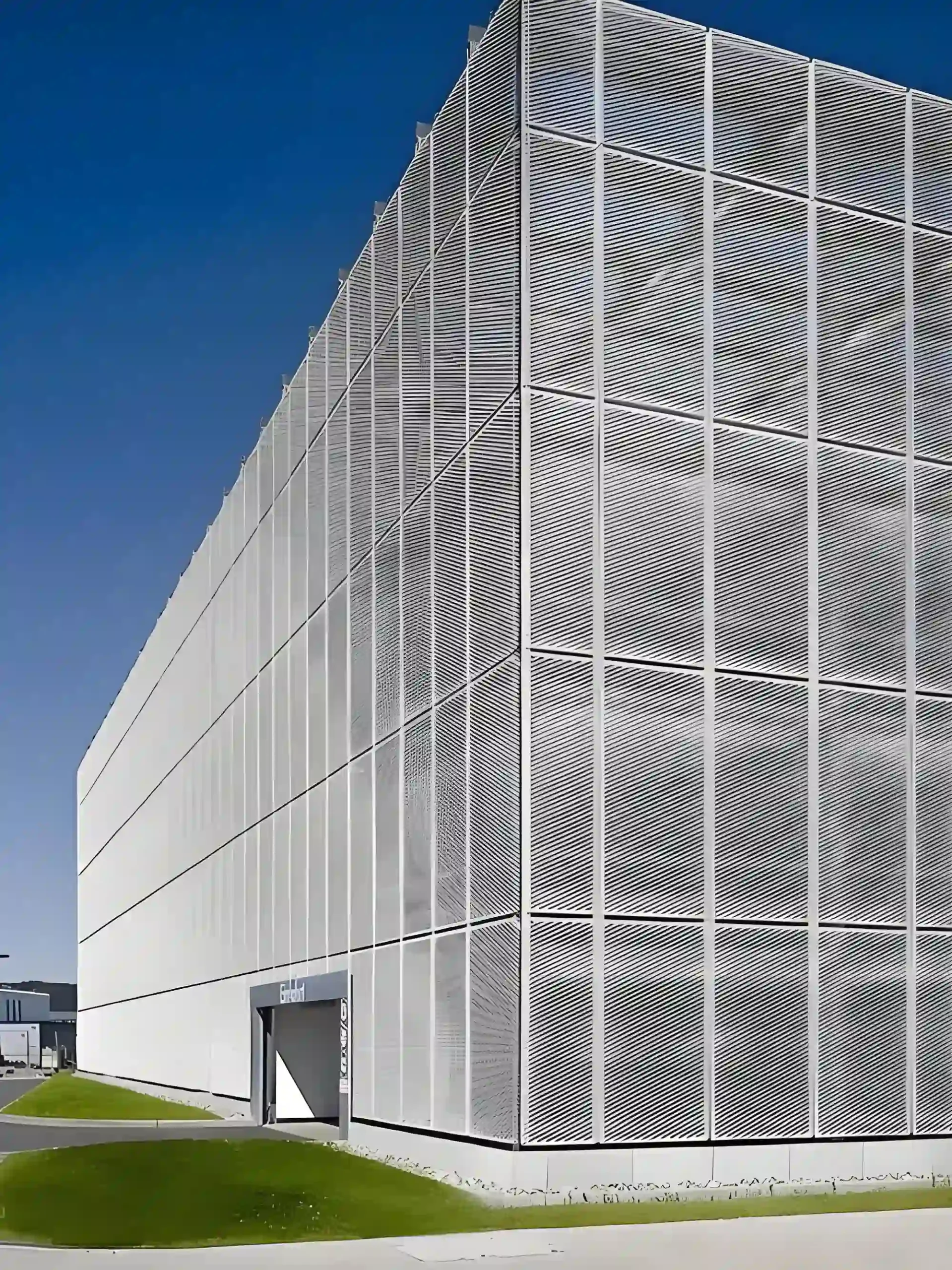
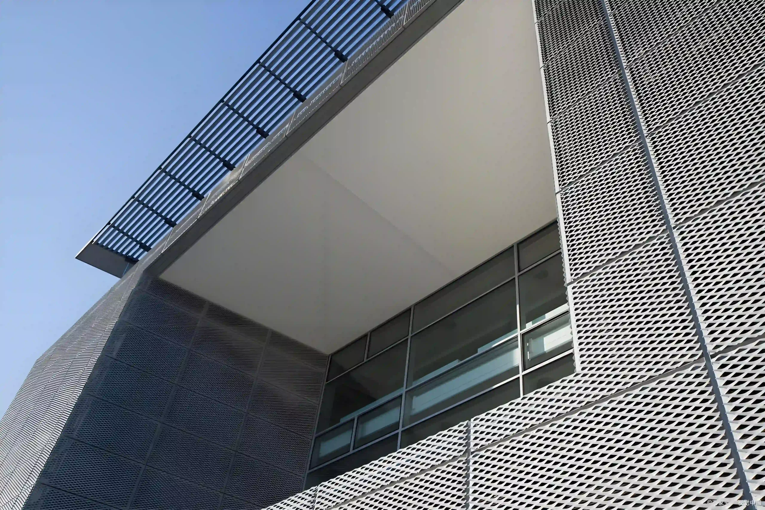
Steel grating façades form open exterior screens that admit air and daylight while providing a defined barrier around buildings and service areas.
Panels can cover ventilated plant rooms, parking structures, utility enclosures, and exposed circulation areas. The grid limits direct access and screens equipment while leaving openings for airflow and filtered daylight.
Selection should consider ventilation demand, daylight, required access restriction, wind loads, panel span, and support connections. Bar orientation, clear openings, corrosion protection, fire requirements, maintenance access, and any required fall protection must be assessed for the complete façade assembly.
Discuss Your Walkway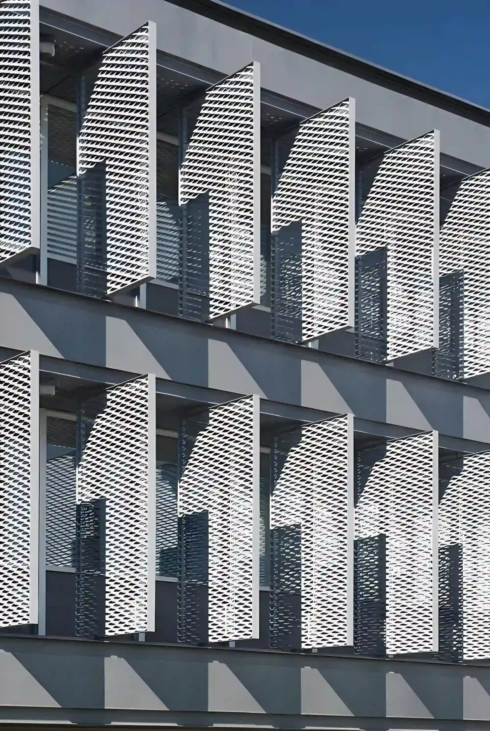
02 / APPLICATION SCENARIOS & REQUIREMENTS
Application Scenarios & Project Requirements
Review the operating conditions, users, loads, environment and project requirements before selecting the appropriate steel grating specification.
Ventilated Plant Rooms
Grating façades enclose mechanical floors while allowing air to reach equipment intakes and exhaust openings. Grid dimensions and stand-off distances should be coordinated with the mechanical designer so the screen does not restrict airflow or encourage exhaust recirculation.
Parking Structure Screens
Exterior grating panels provide an open perimeter for parking levels where natural ventilation is part of the approved design. The screen, supports, and openings must also satisfy applicable edge-protection and vehicle-impact requirements; grating infill alone should not be assumed to provide either function.
Utility Compound Façades
Framed panels screen transformers, pumps, and other building services while preserving inspection sightlines. Bar spacing, panel height, gates, and fixings should reflect the required access control and any equipment-specific clearance or electrical safety requirements.
External Circulation Areas
Grating screens can enclose open stair towers and access balconies without fully blocking daylight or air movement. Where the panels also serve as guards, the entire assembly must meet the applicable height, opening, load, and anchorage requirements.
03 / SPECIFICATIONS & PRODUCT OPTIONS
Common Specifications & Available Options
Compare materials, bearing bar sizes, spacing, surface types, finishes and panel dimensions to match the requirements of the application.
Specifications
| Parameter | Specification / Options |
|---|---|
| Material | Carbon steel flat bars, cross bars, perimeter frames, and support members to the project-specified structural grade. |
| Grating construction |
Welded or press-locked panels with banded edges or an engineered perimeter frame. Select the construction for the required grid pattern, panel stiffness, appearance, and connection details. |
| Surface treatment |
Hot-dip galvanized after fabrication; a compatible exterior coating may be specified over galvanizing for color or additional protection. Confirm the coating system for coastal exposure, industrial emissions, and the intended maintenance interval. |
| Primary flat bar size |
Common starting options include 25 × 3, 30 × 3, 30 × 5, 40 × 5, and 50 × 5 mm. Bar depth × thickness. Final selection depends on panel span, wind loads, frame support, and allowable deflection. |
| Primary bar spacing |
Common center-to-center pitches include 30, 40, and 50 mm. With 5 mm thick bars, the corresponding clear gaps are approximately 25, 35, and 45 mm. Check access restriction using clear gaps, not pitch alone. |
| Transverse bar spacing |
Common pitches include 50 and 100 mm for welded layouts; selected press-locked grids include 30 × 30, 40 × 40, and 40 × 100 mm. Dimensions are center-to-center. Confirm availability for the specified bars and assess openings in both directions. |
| Panel size examples |
Indicative modules include 600 × 1,200, 1,000 × 1,500, 1,000 × 2,000, and 1,200 × 2,400 mm. Width × height. These are layout examples, not unsupported-span ratings; divide large elevations to suit supports, wind design, lifting, and transport. |
| Perimeter frame |
Example angle sections include 30 × 30 × 3 and 40 × 40 × 4 mm; hollow-section options include 40 × 40 × 3 and 50 × 50 × 3 mm. Dimensions are in millimeters. Verify frame members, corners, and connections for the actual panel loads. |
| Bar orientation |
Primary bars arranged vertically or horizontally according to the designed support edges, daylight and viewing requirements, and access-control assessment. Accessible horizontal members may provide footholds; show the load-bearing direction on fabrication drawings. |
| Mounting and clearance |
Bracket projection, façade stand-off, panel joints, and perimeter gaps dimensioned in millimeters on approved elevations and sections. Maintain equipment ventilation, drainage, thermal movement, and cleaning access behind the screen. |
| Fixing and design loads |
Engineered brackets, anchors, and positive panel restraints designed for project wind pressure and suction; M8 or M10 panel bolts may be considered where the connection design permits. Bolt size alone does not establish capacity. Verify fasteners, anchors, substrate, and any required impact or guard loads as one assembly. |
Need a different size? Send your layout for a custom panel review.
Request Your SpecificationThe sizes above are reference examples, not approved combinations for every span. Confirm the bearing direction, loads, clear span and material before ordering. Panel size does not indicate the allowable unsupported span.
WHY USE STEEL GRATING?
Advantages for Steel Grating Applications
Open Ventilation
Grid openings allow air to enter or leave the space behind the façade. Bar depth, pitch, and nearby obstructions can be included in the ventilation assessment for plant rooms and other equipment areas.
Filtered Daylight
The open screen admits daylight to circulation and service areas. Bar orientation and spacing can be chosen to balance useful light with screening of equipment and direct views from outside.
Defined Access Barrier
Rigid steel panels provide physical separation when combined with suitable frames, posts, gates, and secure fixings. Clear openings and perimeter gaps can be specified for the required level of access restriction.
Engineered Wind Resistance
Bars, frames, brackets, and anchors can be sized for the site’s wind pressure and suction. An open grid still attracts wind loads, so connection design remains essential for elevated façade panels.
Exterior Corrosion Protection
Hot-dip galvanizing protects fabricated steel surfaces in suitable outdoor environments. A compatible coating can provide the specified façade color while allowing inspection and repair under the maintenance plan.
Modular Service Access
Identified panels can be made removable where equipment replacement or façade cleaning requires access. Module dimensions and fixing locations can be coordinated with the lifting method and available working space.
04 / INSTALLATION & PROJECT PHOTOS
Installation Guidance & Application Photos
Review the panel layout, support conditions, fixing methods and fabrication details before installation, and refer to the application photos for practical examples.
-
Verify the Façade Layout
Check elevations, structural attachment points, panel marks, wind design, and substrate condition against approved drawings. Confirm ventilation openings, equipment clearances, gates, and any required guard or impact protection before installing supports.
-
Install Supports and Brackets
Set brackets and secondary framing to the specified line, level, and stand-off distance. Install anchors using the approved procedure, maintain movement allowances, and complete the specified sealing at building penetrations.
-
Position and Secure Panels
Lift panels using the approved handling method and match their identification to the elevation layout. Confirm bar orientation, joints, and perimeter gaps, then install every specified restraint. Avoid unapproved cuts to grating, frames, or brackets.
-
Inspect the Completed Façade
Check panel alignment, connection security, exposed edges, coating condition, and access-panel operation. Verify that equipment airflow paths remain clear and complete any specified anchor or assembly acceptance checks before handover.
05 / RELATED REFERENCE & FAQ
Frequently Asked Questions
How can a steel grating façade provide ventilation and security together?
The open grid permits airflow while rigid bars and a secured frame restrict direct entry. These functions require separate checks: ventilation depends on effective open area and airflow resistance, while access control depends on clear openings, panel height, perimeter gaps, gates, and fixing strength.
Which grid sizes are commonly considered for façade panels?
Starting options include 30 × 50, 30 × 100, 40 × 50, and 40 × 100 mm center-to-center grids, depending on the manufacturing method. A closer grid may restrict access more effectively but can affect ventilation, daylight, and weight. State required clear openings separately from bar pitches.
Does an open grating façade need wind-load calculations?
Yes. Openings do not eliminate wind pressure or suction, and load should not be estimated solely from the percentage of solid area. Verify the grating, perimeter frame, brackets, anchors, and supporting structure for the applicable site and building conditions.
Can grating façade panels serve as balcony or stair guards?
They can only when the complete assembly meets the applicable guard requirements. These may cover height, clear openings, climbing, horizontal loads, and anchorage. A panel designed solely as a ventilation screen should not be assumed to provide fall protection.
How should grating screens be placed around mechanical equipment?
Coordinate stand-off distance, grid geometry, and access panels with the equipment supplier and mechanical designer. Keep intake and discharge paths clear, check airflow resistance, and prevent warm exhaust from returning to the intake. Allow enough room to clean the screen and remove service components.
What information is needed to quote custom grating façade panels?
Provide façade elevations, panel dimensions, support locations, design wind loads, and the supporting substrate. Include bar sizes, grid pitches, required clear openings, finish, bracket projection, and access-panel details. State any guard, impact, fire, or security requirements so the complete assembly can be assessed.
06 / PROJECT ENQUIRY
Tell Us About Your Walkway
Share your layout and operating requirements so our team can review the grating, fabrication and supply scope.
Send Drawings by Email Discuss on WhatsAppThe email button opens your mail app. Attach your drawings before sending.
Include these details
- Application location and exposure conditions
- Drawings, panel dimensions and quantities
- Support layout, clear span and design loads
- Material, finish and walking-surface requirements
- Cut-outs, fixings and removable access sections
- Destination, required delivery date and project standards
Already have a specification? Send it with your enquiry.