

01 / APPLICATION OVERVIEW
Steel Grating Ramps for Cargo Handling and Pedestrian Access
Steel grating ramps provide load-bearing transitions for cargo movement and pedestrian access where drainage and a defined walking surface are required.
Installed at loading areas, platform entrances, and changes in floor level, the ramps support personnel, hand carts, and specified handling equipment. The open grid lets rainwater and wash water pass through instead of collecting across the ramp.
Selection should consider ramp slope, clear width, wheel loads, tire or caster contact areas, support span, and bearing direction. Surface profile, grid openings, transition plates, edge protection, corrosion exposure, and fixing details must suit the intended users and equipment.
Discuss Your Walkway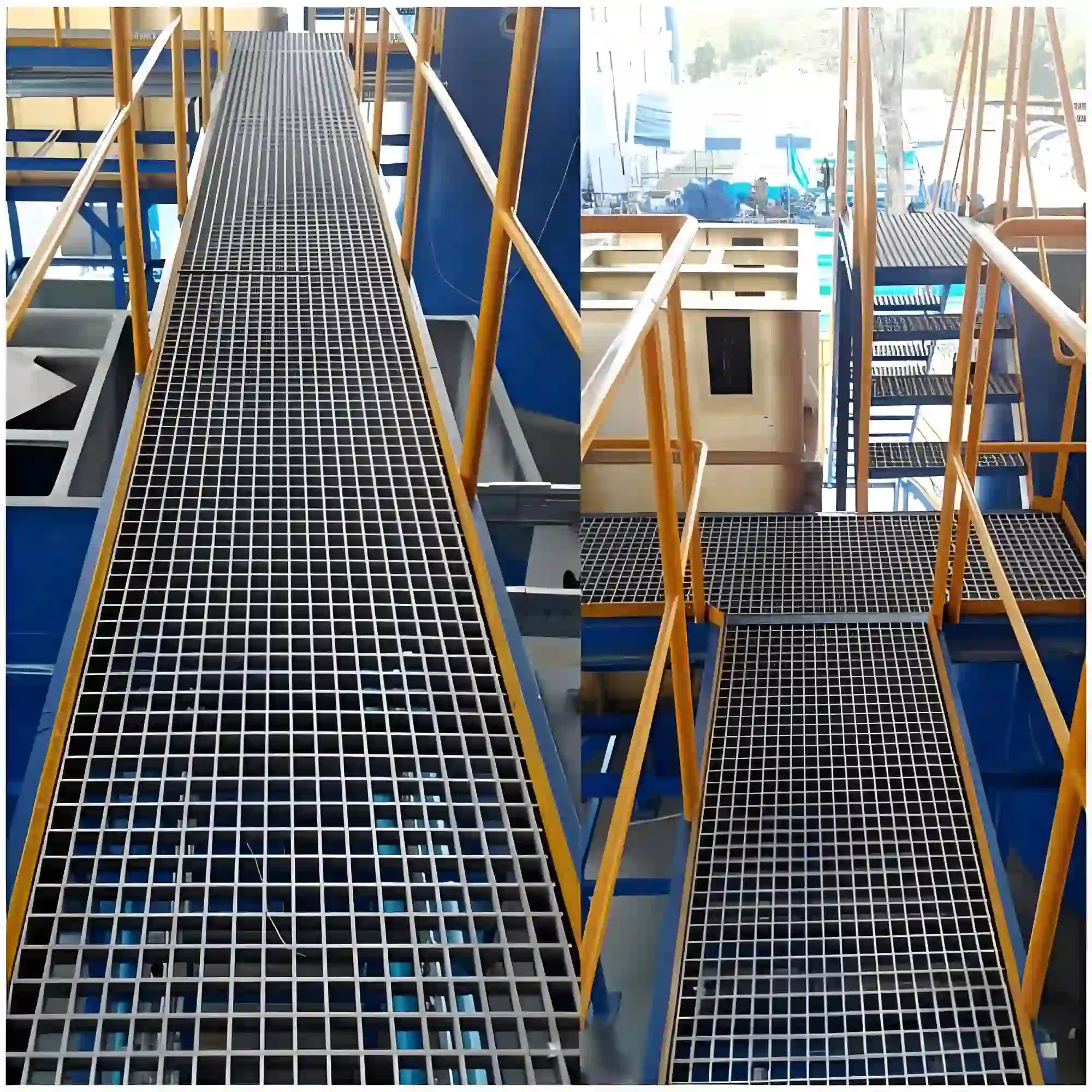
02 / APPLICATION SCENARIOS & REQUIREMENTS
Application Scenarios & Project Requirements
Review the operating conditions, users, loads, environment and project requirements before selecting the appropriate steel grating specification.
Cargo Loading Approaches
Grating ramps connect loading surfaces at different elevations for specified carts or handling vehicles. The complete ramp structure must be checked for wheel loads, braking forces, and repeated traffic, with smooth transitions at both ends.
Hand Cart Transfer Routes
Ramps provide routes for hand carts and material trolleys between production floors and raised platforms. Grid openings and panel joints should suit the smallest caster wheels, while the slope should remain practical for the loaded cart and its operator.
Pedestrian Access Ramps
Grating ramps can provide personnel access at industrial entrances and outdoor service areas. Where the route must be accessible to wheelchair users or the public, slope, landings, handrails, openings, and surface performance require verification against the applicable access requirements.
Equipment Service Ramps
Short ramps can connect maintenance platforms and equipment service areas where tools or components move on wheeled carriers. Their dimensions should account for the load’s center of gravity, handling method, turning space, and clearance at adjoining floors.
03 / SPECIFICATIONS & PRODUCT OPTIONS
Common Specifications & Available Options
Compare materials, bearing bar sizes, spacing, surface types, finishes and panel dimensions to match the requirements of the application.
Specifications
| Parameter | Specification / Options |
|---|---|
| Material | Carbon steel bearing bars, cross bars, frames, and support members to the project-specified structural grade. |
| Surface treatment |
Hot-dip galvanized after fabrication for suitable outdoor or washdown exposure, or a project-specified coating system. Confirm coating suitability for deicing salts, cleaning chemicals, and cargo-area contaminants. |
| Bearing bar size |
Common starting sections include 30 × 5, 32 × 5, 40 × 5, and 50 × 5 mm. Heavy-duty designs may require 50 × 6 or 60 × 6 mm bars. Height × thickness. Verify each section for actual wheel or pedestrian loads, clear span, and allowable deflection. |
| Bearing bar spacing |
Common center-to-center pitches include 20, 30, and 40 mm. With 5 mm thick bars, these produce clear gaps of approximately 15, 25, and 35 mm. Small wheels may require closer spacing or a different surface. |
| Cross bar spacing |
Common center-to-center pitches include 50 and 100 mm, giving grid options such as 20 × 50, 30 × 50, and 30 × 100 mm. Bearing bar pitch × cross bar pitch. Check clear openings and wheel travel direction separately. |
| Ramp width |
Indicative clear widths include 900 and 1,200 mm for personnel routes, or 1,500 and 2,000 mm where the specified handling equipment requires more space. Final width must include operational clearance, edge protection, and any applicable accessibility requirements. |
| Panel size examples |
Fabrication modules may include 600 × 1,000, 1,000 × 1,000, and 1,000 × 1,500 mm. Length along slope × panel width. These are layout examples, not permissible unsupported spans; size panels to the approved support arrangement. |
| Ramp slope and landings |
Rise, horizontal run, and landing dimensions determined from the required access route and equipment capability. Show slope as a ratio or percentage on drawings. No single slope is suitable for all pedestrian, trolley, and vehicle applications. |
| Design loads |
Specify distributed pedestrian loads and, where applicable, maximum wheel loads, contact areas, wheelbase, traffic frequency, and braking forces. Verify the grating, frames, beams, anchors, and supporting structure as one system. |
| Walking surface |
Serrated bearing bars or a project-approved traction surface, with transition plates detailed at the top and bottom. Confirm traction for the expected footwear, tires, moisture, and contaminants; serration alone does not prevent slipping. |
| Bearing direction and fixing |
Bearing bars span between designated ramp supports. Use engineered clips, bolts, or welded connections and provide side restraints, curbs, or handrails where specified. Show support spacing, end bearing, panel joints, and fixing positions on approved drawings. |
Need a different size? Send your layout for a custom panel review.
Request Your SpecificationThe sizes above are reference examples, not approved combinations for every span. Confirm the bearing direction, loads, clear span and material before ordering. Panel size does not indicate the allowable unsupported span.
WHY USE STEEL GRATING?
Advantages for Steel Grating Applications
Defined Load Capacity
Bearing bars, frames, and support spacing can be selected for specified pedestrian and cargo loads. Concentrated wheel loads can be assessed at their actual contact areas and positions along the ramp.
Surface Drainage
Open grating allows rainwater and wash water to pass through the ramp surface. Drainage beneath the ramp should direct water away from entrances, electrical equipment, and areas requiring spill containment.
Traction Surface Options
Serrated bars provide additional contact edges for footwear and suitable tires. The final surface should be assessed against ramp slope, wheel material, expected wetting, and any process residue.
Custom Ramp Geometry
Panel dimensions and support frames can follow the required rise, run, width, and landing positions. Factory-planned transition details help avoid abrupt edges where the ramp meets adjoining floors.
Replaceable Sections
Mechanically secured grating panels can be replaced individually after damage or wear. Removable sections also provide access to supporting steelwork and drainage areas beneath the ramp.
Outdoor Steel Protection
Hot-dip galvanizing after fabrication protects exposed steel surfaces in suitable outdoor conditions. Coating selection and inspection intervals can be matched to the site’s moisture and contaminant exposure.
04 / INSTALLATION & PROJECT PHOTOS
Installation Guidance & Application Photos
Review the panel layout, support conditions, fixing methods and fabrication details before installation, and refer to the application photos for practical examples.
-
Verify Levels and Loads
Measure the upper and lower finished floor levels, available run, required clear width, and landing space. Confirm the intended pedestrians or handling equipment, wheel loads, contact areas, and approved slope before setting out supports.
-
Install the Support Structure
Set beams and frames to the approved slope and support spacing. Anchor them to the verified structural substrate, maintaining the specified clearances and drainage path. Check alignment and stability before placing grating panels.
-
Fit Panels and Transitions
Match panel marks to the ramp layout and place bearing bars across their designated supports. Secure each panel with the specified restraints. Install top and bottom transition plates, side protection, and handrails where detailed.
-
Inspect the Completed Ramp
Check slope, clear width, panel seating, joints, fixings, and transition edges. Verify that wheels or footwear will not catch in openings or gaps. Remove debris, repair coating damage, and complete the specified load and access checks before use.

05 / RELATED REFERENCE & FAQ
Frequently Asked Questions
How is steel grating selected for a cargo-handling ramp?
Provide the maximum loaded equipment weight, individual wheel loads, wheel dimensions, contact areas, travel direction, and operating frequency. The designer must check the grating, supports, connections, and foundations for these loads, including braking or impact effects where applicable. Pedestrian-rated grating should not be assumed suitable for cargo equipment.
Which grating size is suitable for hand carts or pallet trucks?
Bar sections such as 30 × 5 or 40 × 5 mm and pitches of 20 or 30 mm may be considered as starting options. Small, hard caster wheels can impose high local loads or catch in openings. Final selection requires the actual wheel size, contact area, load, and support span; some equipment may need a different ramp surface.
Can a steel grating ramp serve as an accessible pedestrian route?
It can only if the complete ramp meets the applicable accessibility requirements. These may govern slope, landings, clear width, handrails, edge protection, cross-slope, openings, and surface characteristics. Standard industrial grating dimensions do not automatically meet those requirements, so the intended users and local rules must be confirmed before fabrication.
Does serrated grating provide enough slip resistance on a ramp?
Serrations may improve traction, but their effectiveness depends on ramp slope, footwear or tire material, water, oil, and surface wear. Specify the surface through a site assessment and obtain relevant test information where required. Drainage and prompt removal of grease or other deposits remain necessary.
Why are transition plates needed at the ends of a grating ramp?
Transition plates can reduce abrupt changes in level between the grating and adjoining floors. Their shape should suit the wheels and footwear using the ramp, without creating a raised edge or blocking drainage. The plates and their fixings must also carry the loads expected at the ramp entrance and exit.
What information is needed to manufacture a custom grating ramp?
Provide the rise, available horizontal run, required clear width, landing dimensions, and support drawings. Include load data for pedestrians and equipment, wheel specifications, desired grid and surface, corrosion exposure, and fixing details. Show transition edges, handrails, side protection, and drainage arrangements on the approved layout.
06 / PROJECT ENQUIRY
Tell Us About Your Walkway
Share your layout and operating requirements so our team can review the grating, fabrication and supply scope.
Send Drawings by Email Discuss on WhatsAppThe email button opens your mail app. Attach your drawings before sending.
Include these details
- Application location and exposure conditions
- Drawings, panel dimensions and quantities
- Support layout, clear span and design loads
- Material, finish and walking-surface requirements
- Cut-outs, fixings and removable access sections
- Destination, required delivery date and project standards
Already have a specification? Send it with your enquiry.