

01 / APPLICATION OVERVIEW
Steel Grating Floor for High Load Capacity and Slip Resistance
Steel grating floors provide load-bearing, open walking surfaces for industrial platforms, production areas, and maintenance routes where strength and slip resistance are required.
Supported on structural beams, grating panels carry personnel, tools, and specified equipment loads while allowing liquids to drain through. Serrated bearing bars can improve traction in suitable operating conditions, and removable panels provide access to services beneath the floor.
Selection should consider distributed loads, concentrated loads, wheel contact areas, support span, bearing direction, and allowable deflection. Bar spacing, surface profile, corrosion exposure, panel restraint, and conditions below the floor must also suit the intended operation.
Discuss Your Walkway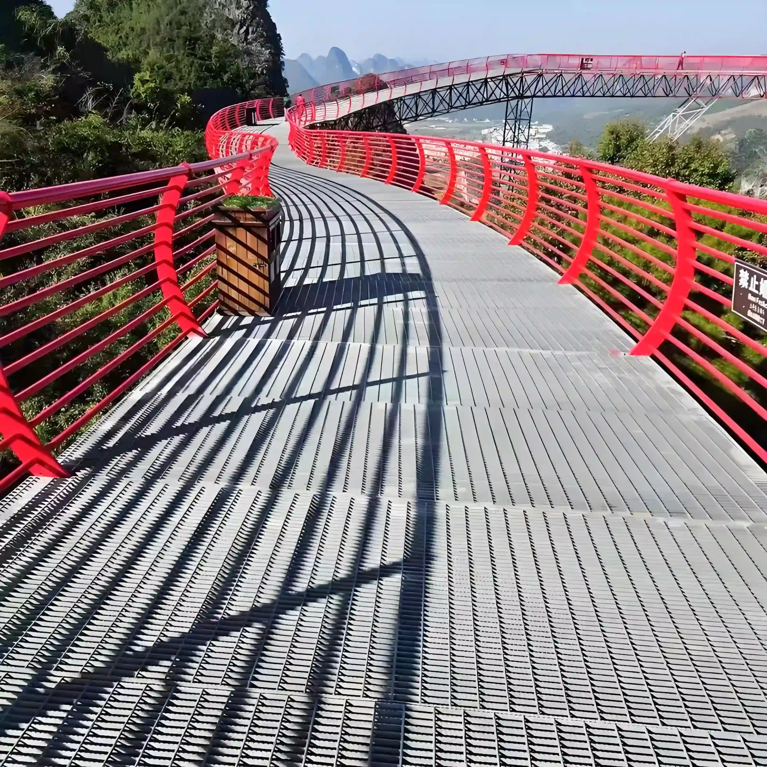
02 / APPLICATION SCENARIOS & REQUIREMENTS
Application Scenarios & Project Requirements
Review the operating conditions, users, loads, environment and project requirements before selecting the appropriate steel grating specification.
Production Floor Platforms
Grating floors provide access around production machinery and operating stations. Bearing bars and supporting beams can be selected for personnel, tools, and defined material loads, with framed openings coordinated around equipment foundations and service penetrations.
Wet Process Areas
Open flooring allows wash water and minor spills to pass into a designated collection area below. Serrated grating may suit wet working conditions, provided surface cleaning, drainage, and protection of lower-level equipment are addressed.
Heavy Maintenance Decks
Maintenance decks can use engineered grating sections where replacement components, lifting accessories, or service equipment create concentrated loads. The design should identify permitted load positions and provide additional supports where equipment feet or handling operations require them.
Industrial Vehicle Crossings
Heavy-duty grating can form designated crossings over channels or service openings where vehicles operate. Wheel loads, tire contact areas, travel direction, braking forces, and repeated loading must be included in the design of panels, supports, and restraints.
03 / SPECIFICATIONS & PRODUCT OPTIONS
Common Specifications & Available Options
Compare materials, bearing bar sizes, spacing, surface types, finishes and panel dimensions to match the requirements of the application.
Specifications
| Parameter | Specification / Options |
|---|---|
| Material | Carbon steel bearing bars, cross bars, and perimeter members to the project-specified structural grades. |
| Surface treatment |
Hot-dip galvanized after fabrication for suitable wet or outdoor exposure, or a project-specified coating system. Confirm compatibility with process liquids, cleaning chemicals, and service temperatures. |
| Bearing bar size |
Common sections include 25 × 3, 30 × 3, 30 × 5, 32 × 5, and 40 × 5 mm; heavier sections may be required for high loads or longer spans. Height × thickness. These examples do not establish a load rating; verify the selected section using applicable load data or calculations. |
| Bearing bar spacing |
Typical center-to-center spacing: 30 or 40 mm, with closer spacing where required for load distribution, footwear, or small-wheel access. Check clear openings separately from bar pitch. |
| Cross bar spacing | Typical center-to-center spacing: 50 or 100 mm, subject to the grating construction and service requirements. |
| Panel dimensions |
Cut-to-size panels manufactured to approved floor layouts, support positions, and equipment openings. Identify the bearing-bar length and cross-bar width, and coordinate panel weight with installation and removal methods. |
| Walking surface |
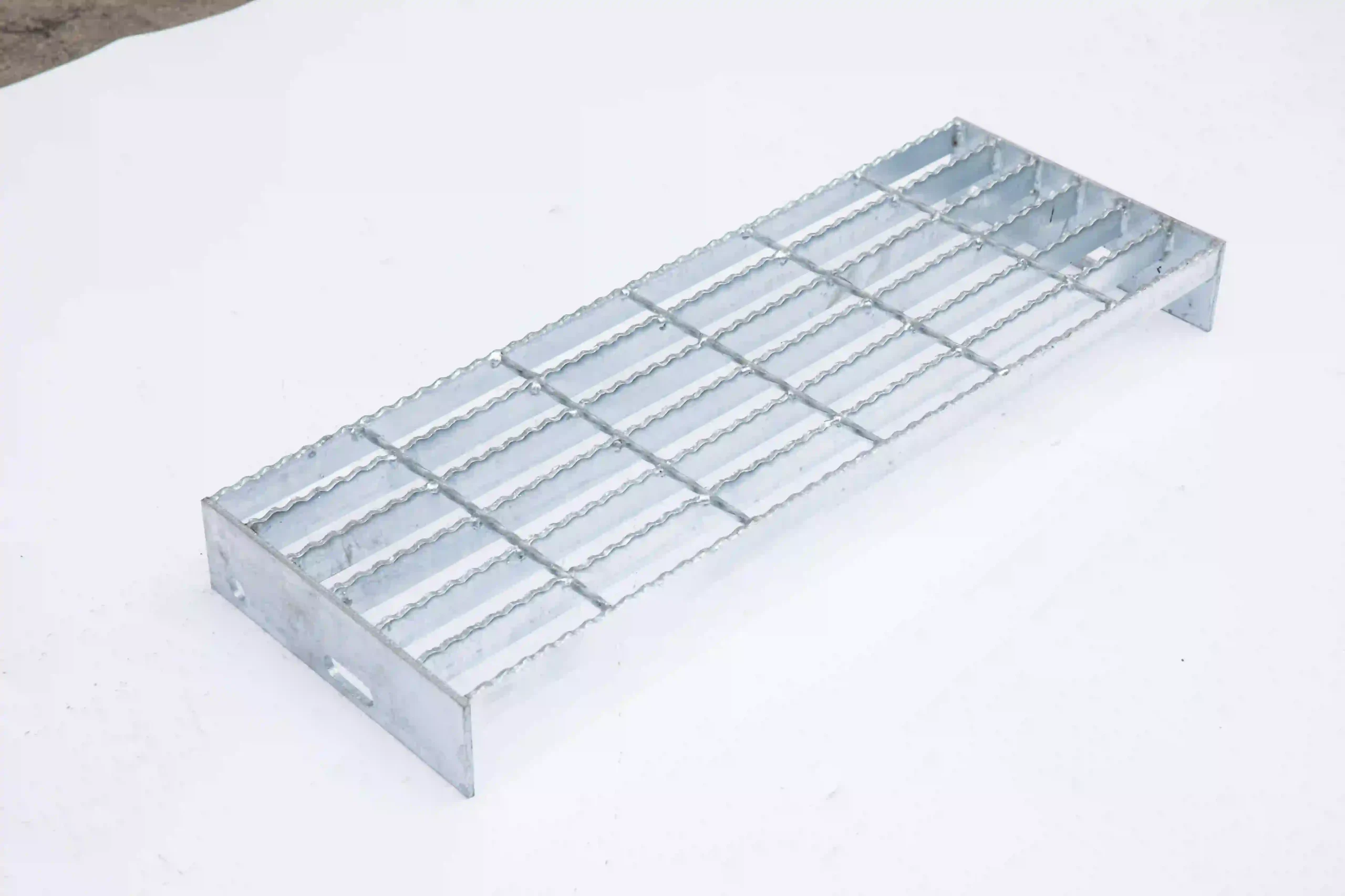
Plain or serrated bearing bars selected for the expected footwear, moisture, and contamination. Use load data applicable to the specified serrated profile. |
| Design loads | Project-defined distributed loads, concentrated loads, contact areas, and deflection limits, with dynamic or repeated loading considered where applicable. |
| Bearing direction |
Bearing bars span between designated structural supports with the specified end bearing. Show supported edges, clear spans, and load-bearing direction on fabrication drawings. |
| Edge and opening treatment | Banded panel edges, framed cut-outs, and toe plates where required, with additional structural support for interrupted bearing bars. |
| Fixing | Engineered grating clips, bolted restraints, or approved welded connections selected for movement, uplift, vibration, and maintenance access requirements. |
Need a different size? Send your layout for a custom panel review.
Request Your SpecificationThe sizes above are reference examples, not approved combinations for every span. Confirm the bearing direction, loads, clear span and material before ordering. Panel size does not indicate the allowable unsupported span.
WHY USE STEEL GRATING?
Advantages for Steel Grating Applications
Engineered Load Capacity
Bearing bar depth, thickness, spacing, and support span can be selected for defined operating loads. This allows the flooring design to address both distributed loading and concentrated loads from equipment or handling activities.
Serrated Traction Option
Serrated bars provide additional contact edges that can improve footwear grip under suitable conditions. Surface selection should reflect the actual contamination and cleaning regime, since oil, grease, or ice can still create slip hazards.
Reduced Surface Pooling
Openings allow water to leave the walking surface instead of collecting across a solid floor. The drainage arrangement below can be coordinated with spill collection and protection of occupied areas or equipment.
Controlled Floor Deflection
Bar sections and support spacing can be designed to limit deflection under service loads. Checking stiffness alongside strength helps provide a stable floor for personnel and the specified maintenance operations.
Access Beneath the Floor
Mechanically secured panels can be removed individually to inspect underlying steelwork, drainage, or services. Panel dimensions and lifting provisions can be planned around the available handling equipment and maintenance clearances.
Coordinated Equipment Openings
Factory-fabricated panels can fit around columns, pipes, and machinery interfaces. Framed openings and local supports preserve the intended load path while reducing the need to modify load-bearing bars on site.
04 / INSTALLATION & PROJECT PHOTOS
Installation Guidance & Application Photos
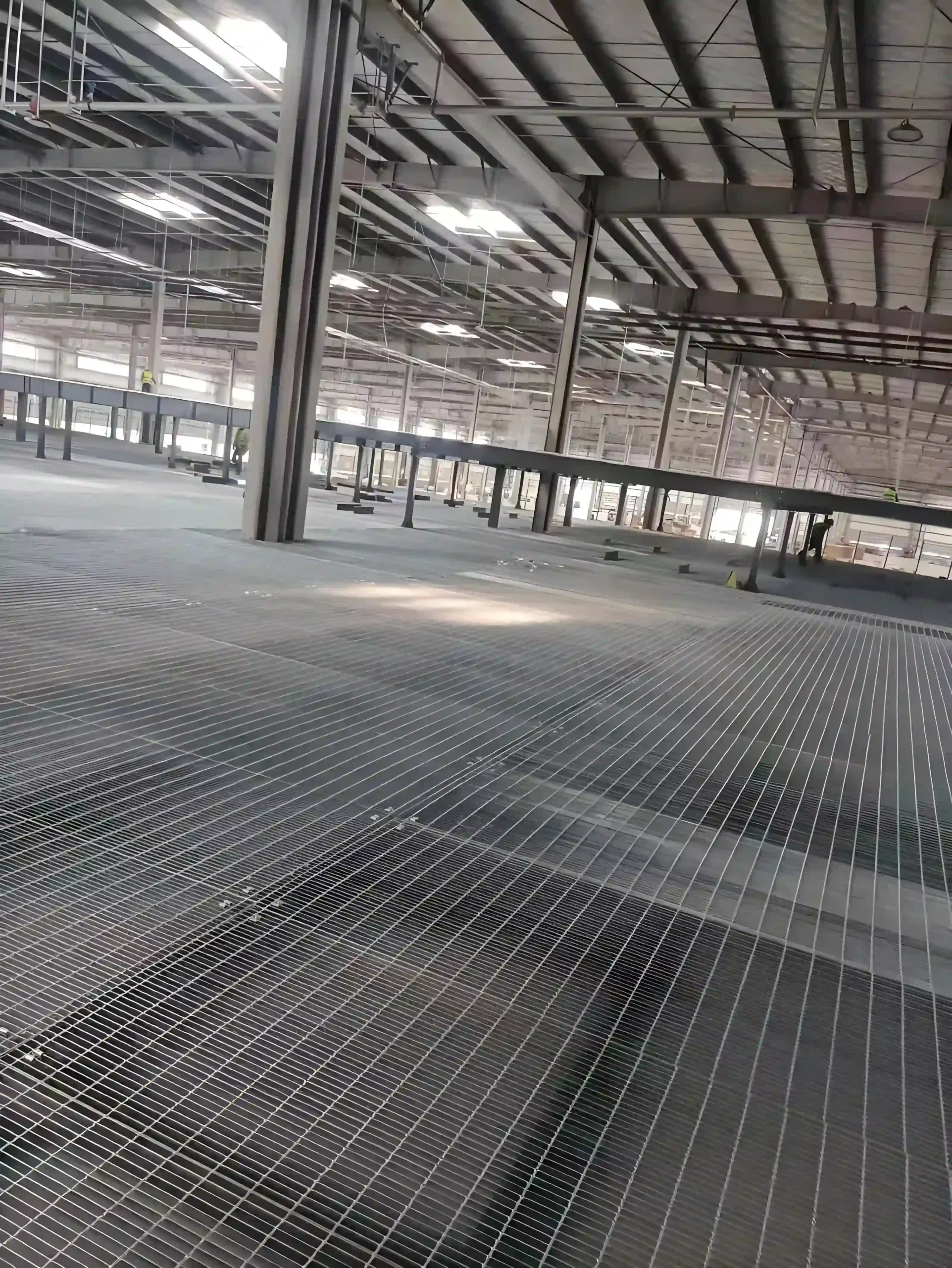
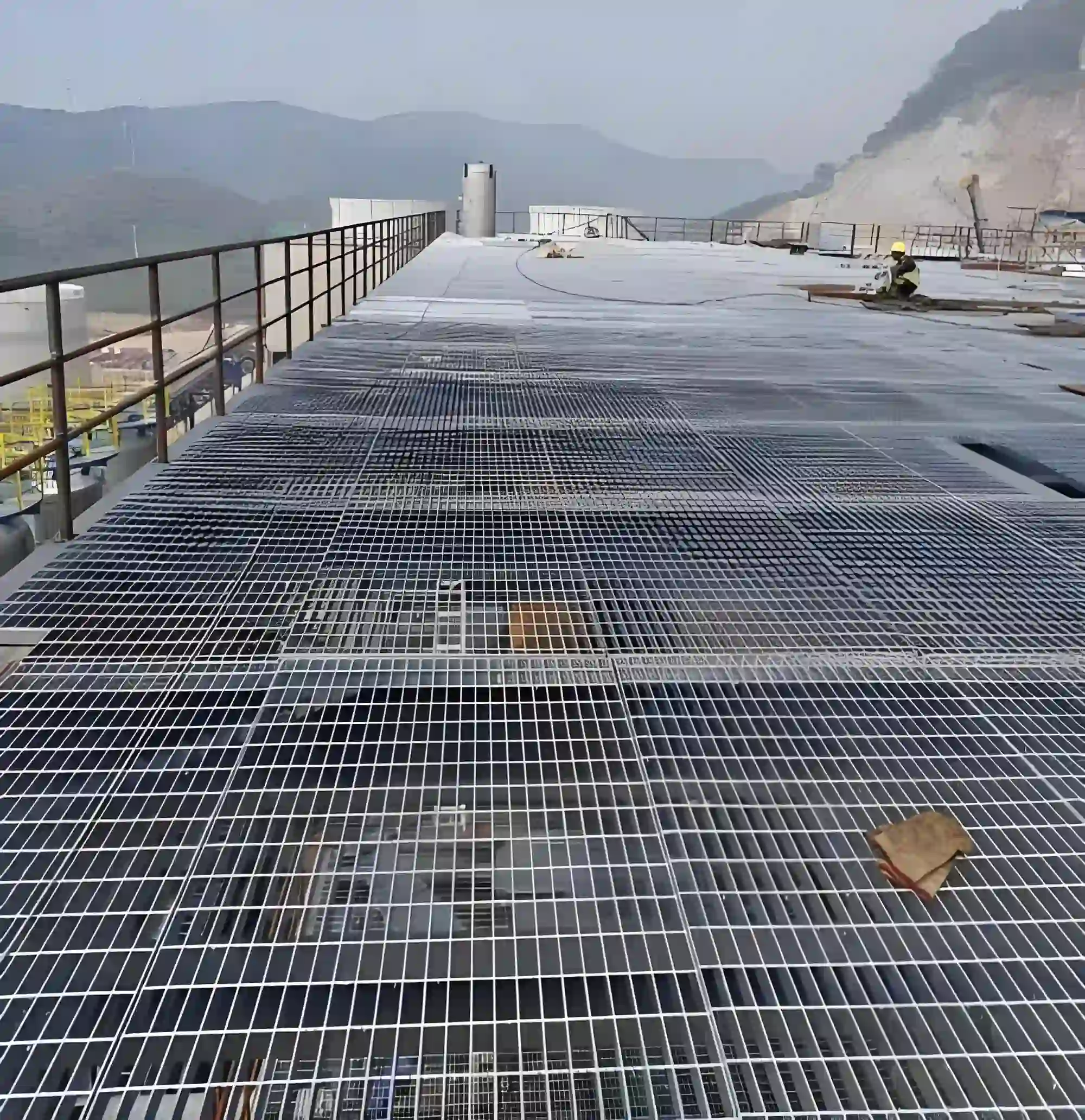
Review the panel layout, support conditions, fixing methods and fabrication details before installation, and refer to the application photos for practical examples.
-
Verify Loads and Supports
Check beam positions, clear spans, support widths, elevations, and approved floor loads. Confirm any equipment contact areas or vehicle routes and verify that the supporting structure is ready to receive the grating and its intended loads.
-
Set Out the Panels
Match panel identification to the floor layout and ensure bearing bars span between the designated supports. Check end bearing, joints, cut-outs, toe plates, and removable sections. Provide the approved support details around interrupted bearing bars.
-
Secure the Flooring
Seat panels evenly and install specified restraints at the approved locations. Use the required fastener tightening or welding procedure, and keep fixings compatible with the surface treatment. Do not cut bars or alter supports without structural approval.
-
Inspect Before Loading
Check for rocking panels, raised joints, loose restraints, sharp edges, and damaged coatings. Remove debris and contaminants, verify drainage paths, and complete the specified acceptance checks. Confirm operational load limits before equipment or materials are placed on the floor.
05 / RELATED REFERENCE & FAQ
Frequently Asked Questions
How is the load capacity of a steel grating floor determined?
Capacity depends on the steel grade, bearing bar section, spacing, clear span, support conditions, and load arrangement. The design must check strength and deflection for both distributed and concentrated loads. A capacity stated for uniform loading cannot automatically be applied to an equipment foot or vehicle wheel.
Does serrated grating prevent slipping on wet or oily floors?
Serrations can improve traction, but they do not guarantee safe footing under every condition. Performance depends on footwear, contaminants, surface wear, and cleaning. Specify the surface through a site slip-risk assessment and request relevant test information where required, while maintaining prompt removal of oil, grease, and other deposits.
Can steel grating floors support forklifts or pallet trucks?
They can when the complete flooring system is designed for the actual wheel loads and operating conditions. Small, hard wheels can impose high localized loads and interact poorly with large openings. Provide wheel dimensions, contact areas, travel direction, traffic frequency, and braking conditions before selecting the grating and restraints.
Does serration affect the structural capacity of bearing bars?
Serrations alter the effective bar section and may reduce capacity compared with an otherwise similar plain bar. Use manufacturer load tables or engineering calculations that specifically cover the selected serrated profile. Do not assume that plain and serrated bars of the same nominal dimensions have identical ratings.
Why is bearing bar direction important for floor installation?
Bearing bars carry loads across the span to the structural supports. Cross bars mainly connect and stabilize them, and should not be assumed to provide equivalent spanning capacity. Incorrect orientation or unsupported cut bars can compromise the floor, so the installation must follow the marked bearing direction and approved support layout.
What information is needed to specify a high-load grating floor?
Provide the floor plan, support locations, clear spans, load magnitudes, and contact areas. Include vehicle or equipment details, deflection limits, required surface profile, corrosion exposure, and opening restrictions. Identify cut-outs, removable panels, and restraint requirements so the grating and supporting structure can be assessed together.
06 / PROJECT ENQUIRY
Tell Us About Your Walkway
Share your layout and operating requirements so our team can review the grating, fabrication and supply scope.
Send Drawings by Email Discuss on WhatsAppThe email button opens your mail app. Attach your drawings before sending.
Include these details
- Application location and exposure conditions
- Drawings, panel dimensions and quantities
- Support layout, clear span and design loads
- Material, finish and walking-surface requirements
- Cut-outs, fixings and removable access sections
- Destination, required delivery date and project standards
Already have a specification? Send it with your enquiry.