

01 / APPLICATION OVERVIEW
Waterjet Table Steel Grating for Cutting Applications
Waterjet table steel grating supports workpieces above the catch tank during abrasive and pure-water cutting while allowing water and spent abrasive to pass through.
Removable panels are installed across the cutting bed beneath plate, sheet, and fabricated parts. They keep material at the required cutting height and provide access to the tank for abrasive removal and support replacement.
Selection should consider machine cutting area, workpiece weight, part size, support spacing, nozzle clearance, and the path of the cutting jet. Bar wear, small-part retention, tank access, and compatibility with the machine’s existing supports must also be checked.
Discuss Your Walkway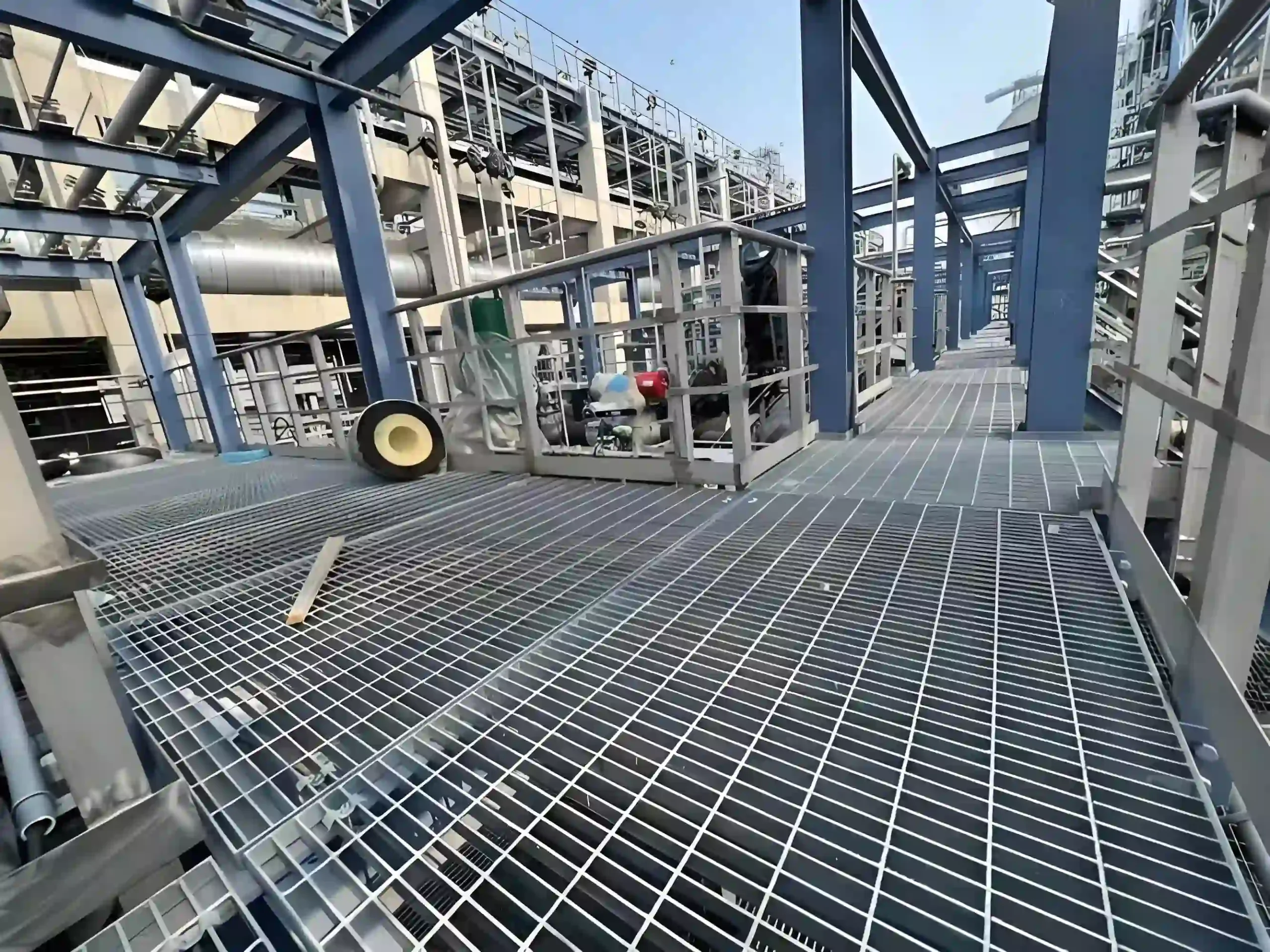
02 / APPLICATION SCENARIOS & REQUIREMENTS
Application Scenarios & Project Requirements
Review the operating conditions, users, loads, environment and project requirements before selecting the appropriate steel grating specification.
Metal Plate Cutting
Grating supports steel, aluminum, and other metal plates above the waterjet catch tank. Bar spacing should provide stable contact beneath the workpiece without placing support members where repeated cuts will cause unnecessary wear.
Sheet and Profile Cutting
Removable panels support sheet stock and fabricated profiles during cutting. Fixtures or supplementary supports may be needed for narrow material, irregular shapes, or sections that could tip as cuts separate them from the parent workpiece.
Heavy Workpiece Support
Thicker plate and large components require support bars and tank framing verified for their total weight and contact points. The loading plan should also account for material placement and removal, particularly when lifting equipment is used.
Replaceable Cutting Bed Sections
Modular grating sections can be removed when repeated jet strikes damage the bars or abrasive accumulates below the bed. Dividing the table into manageable panels allows localized replacement and provides access for catch-tank cleaning.
03 / SPECIFICATIONS & PRODUCT OPTIONS
Common Specifications & Available Options
Compare materials, bearing bar sizes, spacing, surface types, finishes and panel dimensions to match the requirements of the application.
Specifications
| Parameter | Specification / Options |
|---|---|
| Material |
Carbon steel for replaceable cutting-bed panels; stainless steel may be specified where the water chemistry or maintenance conditions warrant it. Confirm material compatibility with the machine manufacturer’s tank and cutting process. |
| Grating construction |
Welded or mechanically assembled open-grid panels with replaceable load-bearing members. Confirm the construction with the machine’s support layout and expected jet-strike pattern. |
| Bearing bar size |
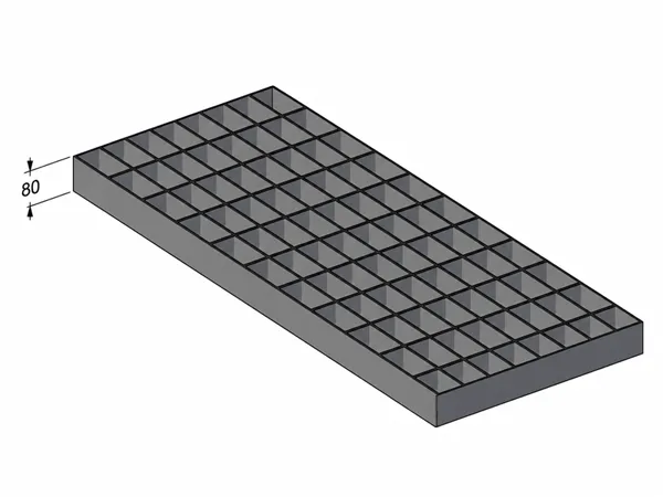
Common starting sections for fabricated panels include 30 × 5, 40 × 5, and 50 × 5 mm; heavier sections may be required for larger workpieces or longer spans. Bar height × thickness. Final size depends on workpiece loading and the clear span between tank supports. |
| Bearing bar spacing |
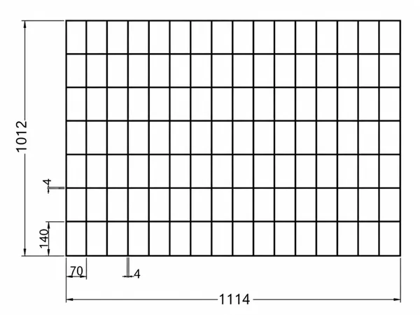
Example center-to-center pitches include 30, 40, and 50 mm. With 5 mm thick bars, these give clear gaps of approximately 25, 35, and 45 mm respectively. Smaller parts may need a separate sacrificial backing or fixture. |
| Cross bar spacing |
Example center-to-center pitches include 50 and 100 mm, giving layout options such as 30 × 50, 40 × 50, and 40 × 100 mm. Bearing bar pitch × cross bar pitch. Confirm that cross bars do not obstruct panel seating or tank maintenance. |
| Panel size examples |
Practical modular sizes may include 500 × 1,000, 1,000 × 1,000, and 1,000 × 2,000 mm. Length × width. Actual panel dimensions must match the machine cutting area, tank supports, lifting access, and approved bed layout. |
| Support span |
Set by the existing tank rails or added support members rather than by the overall panel length. Record each clear span in millimeters and verify bar strength and deflection for the heaviest planned workpiece. |
| Workpiece loading |
Specify maximum workpiece mass, dimensions, and contact arrangement for each cutting setup. A concentrated load from a small part or fixture differs from a plate resting across several bars. |
| Surface treatment |
Mill-finish carbon steel is an option for sacrificial bars; galvanized or other finishes require process review. Direct jet strikes and abrasive wear can remove coatings, so a protective finish should not be assumed to last on the cutting surface. |
| Edge and bearing direction |
Banded or framed edges sized to seat on the tank supports, with bearing bars spanning between those supports. Confirm top elevation, end bearing, and clearance from the nozzle’s operating range. |
| Fixing and replacement |
Lift-out panels or project-specified restraints that prevent movement during loading while allowing removal for cleaning and replacement. Keep lifting provisions accessible and select panel weights compatible with the planned handling method. |
Need a different size? Send your layout for a custom panel review.
Request Your SpecificationThe sizes above are reference examples, not approved combinations for every span. Confirm the bearing direction, loads, clear span and material before ordering. Panel size does not indicate the allowable unsupported span.
WHY USE STEEL GRATING?
Advantages for Steel Grating Applications
Stable Workpiece Support
Bearing bars distribute the weight of suitable plates and components to the tank supports. Bar spacing and panel stiffness can be selected to limit workpiece movement during cutting.
Open Water Passage
Grid openings allow cutting water and spent abrasive to enter the catch tank. The bed layout should preserve the machine’s intended water level and collection path.
Localized Replacement
Individual panels can be exchanged when repeated cutting damages their bars. Modular construction avoids removing the entire bed to replace a worn section.
Catch-Tank Access
Lift-out sections expose the tank for abrasive removal, inspection, and cleaning. Panel dimensions can be coordinated with available lifting equipment and the machine’s maintenance openings.
Adaptable Support Layout
Bar pitch and panel divisions can be matched to common workpiece sizes and the existing tank rails. Supplementary fixtures can support small or irregular parts where the standard grid is insufficient.
Defined Bed Elevation
Fabricated panels provide a consistent seating height across the table when installed on aligned supports. Regular inspection and replacement help prevent worn or displaced bars from affecting workpiece position.
04 / INSTALLATION & PROJECT PHOTOS
Installation Guidance & Application Photos
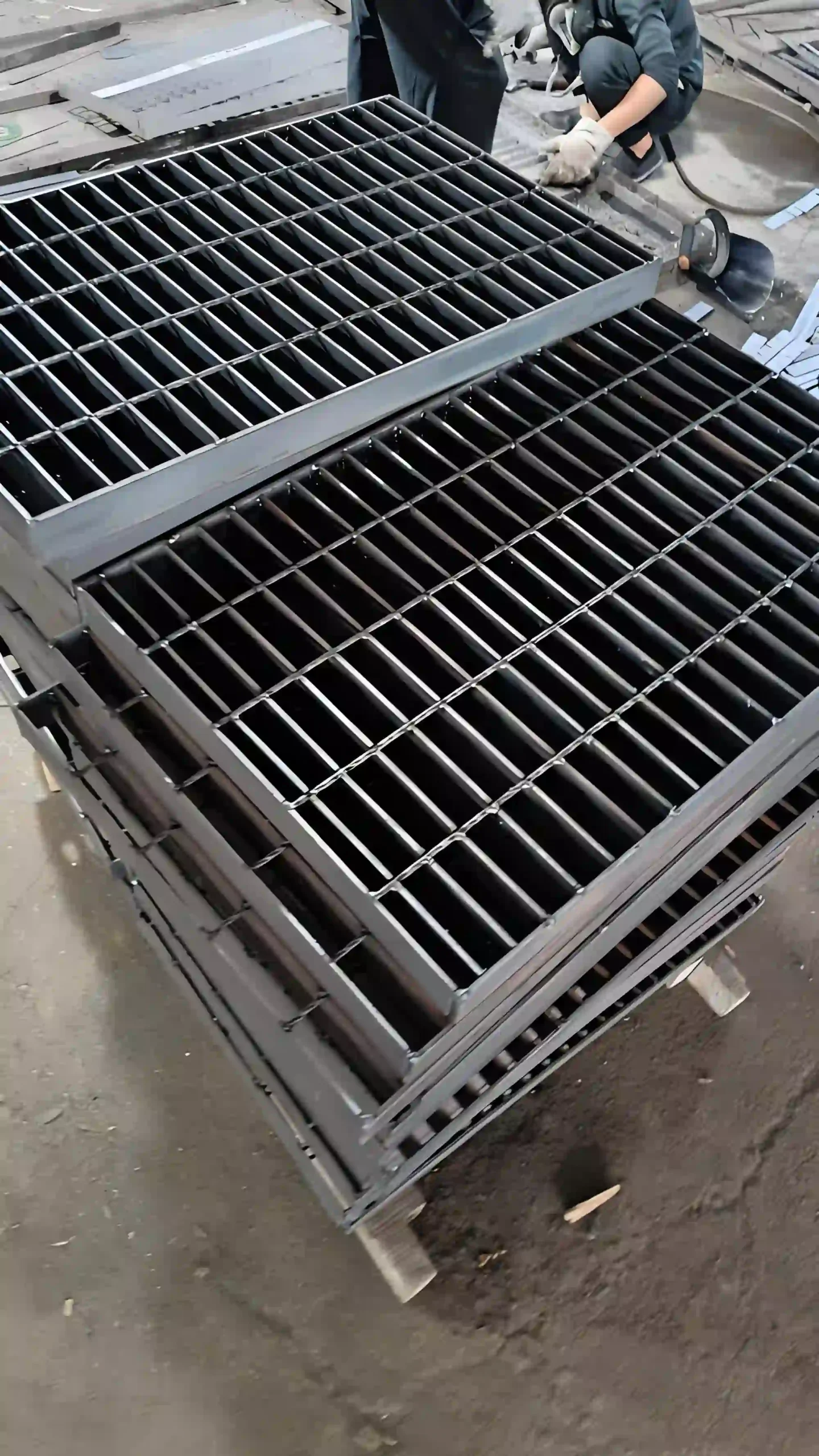
Review the panel layout, support conditions, fixing methods and fabrication details before installation, and refer to the application photos for practical examples.
-
Verify the Table Layout
Measure the cutting area, tank supports, clear spans, and required bed elevation. Confirm machine travel limits, nozzle clearance, and the maximum workpiece load before finalizing panel dimensions.
-
Prepare the Catch Tank
Follow the machine’s isolation procedure. Remove worn support sections and accumulated abrasive as required, then inspect tank rails for damage, corrosion, or uneven seating surfaces.
-
Place and Restrain Panels
Match panel identification to the layout and position bearing bars across their designated supports. Seat each panel evenly, maintain specified joints, and fit restraints where required. Keep the nozzle travel path and maintenance access clear.
-
Check Before Cutting
Inspect panel stability and top elevation, then confirm that the planned workpiece is adequately supported. Check for loose bars, sharp damage, and trapped debris. Use supplementary support where small parts could fall through or shift during cutting.
05 / RELATED REFERENCE & FAQ
Frequently Asked Questions
What bar size is suitable for a waterjet cutting table?
Sections such as 30 × 5, 40 × 5, and 50 × 5 mm can be considered for fabricated support panels. The correct size depends on the clear span, workpiece mass, contact area, and acceptable deflection. Confirm the machine’s bed height and support arrangement before choosing a section.
Which grid spacing should be used for waterjet cutting?
Example bearing bar pitches include 30, 40, and 50 mm, often paired with 50 or 100 mm cross bar pitches. Select the grid according to the workpiece sizes and support points used most often. Small cut parts can still fall through and may require a separate backing surface or fixture.
Can ordinary walkway grating be used as a waterjet table bed?
Only after checking its dimensions, support direction, load capacity, and compatibility with the machine. Waterjet beds are exposed to direct jet strikes and abrasive wear, so their bars are consumable. A walkway panel may also have unsuitable top elevation, grid openings, or removal details.
Is galvanized grating suitable for the cutting surface?
Galvanizing may protect surfaces away from direct cutting, but the jet and abrasive can rapidly remove zinc from struck bars. Mill-finish replaceable carbon steel is one option for the cutting bed. Review coating debris, water treatment, and corrosion requirements before specifying galvanized panels.
How often should waterjet table grating be replaced?
Replacement frequency depends on cutting hours, material thickness, programmed cut paths, and abrasive use. Inspect bars for deep cuts, loss of support, bending, or unstable panels during routine maintenance. Replace affected sections before they can no longer hold workpieces at the required height.
What information is needed to manufacture replacement panels?
Provide the machine model or approved bed drawing, cutting-area dimensions, support rail positions, panel layout, and required top elevation. Include maximum workpiece weight, preferred bar spacing, material, edge details, and handling limits. Measurements of an existing panel should be checked against the tank before fabrication.
06 / PROJECT ENQUIRY
Tell Us About Your Walkway
Share your layout and operating requirements so our team can review the grating, fabrication and supply scope.
Send Drawings by Email Discuss on WhatsAppThe email button opens your mail app. Attach your drawings before sending.
Include these details
- Application location and exposure conditions
- Drawings, panel dimensions and quantities
- Support layout, clear span and design loads
- Material, finish and walking-surface requirements
- Cut-outs, fixings and removable access sections
- Destination, required delivery date and project standards
Already have a specification? Send it with your enquiry.