

Bar grating size is defined by more than the overall panel length and width. The bearing bar depth, bearing bar thickness, bar spacing, cross bar spacing, mesh pattern, material, support span, and surface type all affect the final weight, open area, drainage performance, and load capacity. Common industrial specifications include 25 × 3 mm, 30 × 3 mm, 32 × 5 mm, and 40 × 5 mm bearing bars, with 30/100 mm and 30/50 mm mesh patterns widely used in metric projects. Choosing the right bar grating size means matching the panel to its actual span and load instead of selecting only by appearance.Need custom sizes for your project? See our Steel Grating Manufacturing Capabilities.
Bar grating is an open-grid metal flooring product made from load-bearing bars and cross bars. The vertical bearing bars carry the main applied load between supports. Cross bars connect the bearing bars and create the visible mesh pattern.
A complete bar grating size description normally includes:
For example, a specification such as “welded steel bar grating, 30 × 3 mm, 30/100 mm mesh, serrated, hot-dip galvanized, 1000 × 6000 mm panel” contains much more useful information than simply saying “steel grate.”
The bearing bars must run in the span direction between supports. If a grating panel is installed with the bearing bars in the wrong direction, its load capacity and stiffness can be greatly reduced.
When viewing a rectangular panel, the longer dimension is often the bearing bar direction on stock panels, but this should never be assumed. The approved fabrication drawing should clearly mark the bearing bar direction and support locations.
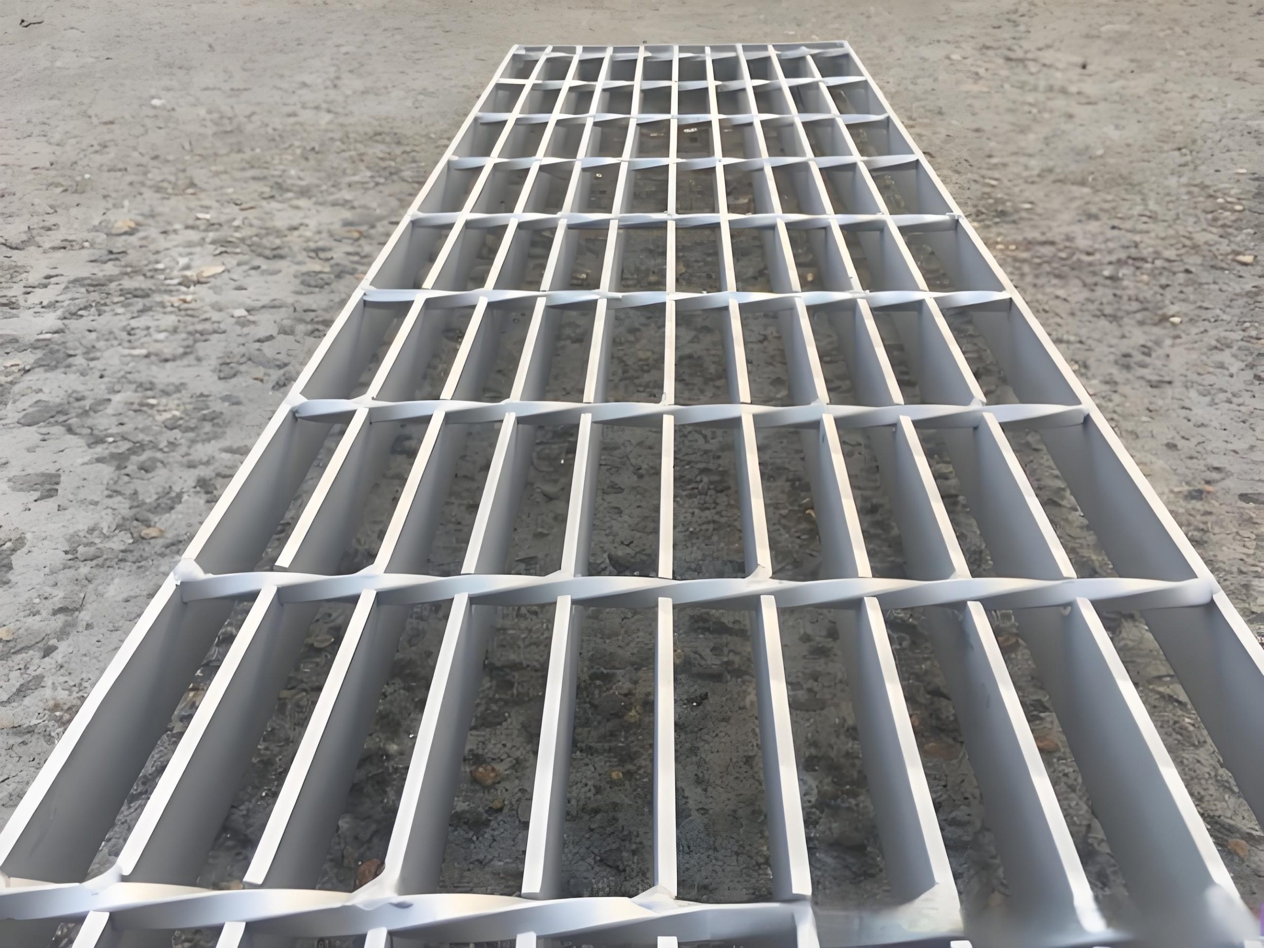
Standard bar grating dimensions vary by manufacturer, country, material, and construction method. Metric production commonly uses millimeter dimensions, while North American products often use inch-based bearing bar and spacing designations.
Common metric bearing bar sizes include 20 × 3 mm, 25 × 3 mm, 25 × 5 mm, 30 × 3 mm, 30 × 5 mm, 32 × 3 mm, 32 × 5 mm, 40 × 3 mm, 40 × 5 mm, and 50 × 5 mm.
| Metric Bearing Bar Size | Meaning | Typical Use |
|---|---|---|
| 20 × 3 mm | 20 mm deep and 3 mm thick | Short-span light-duty access areas |
| 25 × 3 mm | 25 mm deep and 3 mm thick | Light to standard industrial walkways |
| 25 × 5 mm | 25 mm deep and 5 mm thick | Short spans requiring a stronger bar section |
| 30 × 3 mm | 30 mm deep and 3 mm thick | General industrial platforms and walkways |
| 30 × 5 mm | 30 mm deep and 5 mm thick | Higher traffic and higher concentrated loads |
| 32 × 3 mm | 32 mm deep and 3 mm thick | Common metric industrial grating system |
| 32 × 5 mm | 32 mm deep and 5 mm thick | Medium-duty platforms and walkways |
| 40 × 3 mm | 40 mm deep and 3 mm thick | Longer spans and lower deflection requirements |
| 40 × 5 mm | 40 mm deep and 5 mm thick | Heavy-duty industrial access routes |
| 50 × 5 mm or larger | 50 mm deep and 5 mm thick or above | Long-span and specially engineered applications |
Common imperial bearing bar heights include 3/4 inch, 1 inch, 1-1/4 inch, 1-1/2 inch, 1-3/4 inch, 2 inches, and 2-1/2 inches. Typical bearing bar thicknesses include 1/8 inch, 3/16 inch, and 1/4 inch.
| Imperial Bearing Bar Size | Approximate Metric Equivalent | Typical Use |
|---|---|---|
| 3/4 × 1/8 in | 19 × 3 mm | Light-duty grating and short-span flooring |
| 3/4 × 3/16 in | 19 × 5 mm | Standard light industrial applications |
| 1 × 3/16 in | 25 × 5 mm | General walkway and platform grating |
| 1-1/4 × 3/16 in | 32 × 5 mm | Standard-duty industrial platforms |
| 1-1/2 × 3/16 in | 38 × 5 mm | Longer spans and higher service loads |
| 1-1/2 × 1/4 in | 38 × 6 mm | Medium to heavy-duty grating |
| 2 × 1/4 in | 51 × 6 mm | Heavy-duty and longer-span applications |
Bearing bar depth and thickness are the main dimensions used to select bar grating strength. The depth is the vertical height of the bearing bar. The thickness is the horizontal thickness of the bar.
Increasing bearing bar depth usually improves bending stiffness significantly. A deeper bar can often span farther or support more load than a shallower bar of the same thickness.
For example, a 40 mm deep bearing bar generally has much greater stiffness than a 25 mm deep bar of equal thickness. This is why longer-span platforms often use deeper bars instead of only increasing thickness.
Increasing thickness improves the cross-sectional area of the bearing bar. Thicker bars can provide greater strength, more corrosion allowance, better impact resistance, and stronger weld areas.
The most economical selection is usually the smallest bearing bar that satisfies both strength and deflection requirements. Oversizing every panel adds weight, material cost, galvanizing cost, freight cost, and installation effort.
Rectangular bearing bars are common for steel, galvanized steel, and stainless steel grating. Aluminum grating may use rectangular bars, I-bars, T-bars, or special extruded profiles.
| Bearing Bar Type | Main Feature | Typical Application |
|---|---|---|
| Rectangular bar | Simple, strong, widely available | Steel, galvanized steel, stainless steel grating |
| I-bar | Reduced weight with structural depth | Aluminum walkways and lightweight access systems |
| T-bar | Profiled top and efficient aluminum design | Architectural and lightweight aluminum grating |
| Serrated rectangular bar | Notched top surface for added traction | Outdoor, wet, oily, or muddy access areas |
Bearing bar spacing is measured from the center of one bearing bar to the center of the next. It affects the clear opening between bars, the number of load-bearing bars per square meter, panel weight, open area, drainage, and local load distribution.
| Bearing Bar Pitch | General Characteristic | Typical Use |
|---|---|---|
| 25 mm | Close spacing and smaller openings | Controlled opening requirements and close-mesh floors |
| 30 mm | Balanced strength, drainage, and open area | General industrial walkways and platforms |
| 32 mm | Common regional metric spacing | Industrial flooring and platform systems |
| 34 mm | Moderate spacing | Manufacturer-specific grating systems |
| 40 mm | More open grid and lower material weight | Light to standard-duty applications where permitted |
In North American bar grating systems, common bearing bar spacing designations include 19 space, 15 space, 11 space, 8 space, and 7 space patterns.
| Spacing Designation | Center-to-Center Spacing | General Description |
|---|---|---|
| 19 space | 1-3/16 in | Common standard-duty bar grating spacing |
| 15 space | 15/16 in | Closer bearing bar spacing with smaller openings |
| 11 space | 11/16 in | Close-mesh pattern for smaller opening requirements |
| 8 space | 1/2 in | Very close spacing for specialized access needs |
| 7 space | 7/16 in | Close-mesh grating with reduced opening size |
Closer spacing generally increases the grating weight because more bearing bars are used in the same area. It may also improve local load distribution, but the final load capacity must still be checked against the applicable manufacturer load table.
Cross bars connect the bearing bars and maintain the grating pattern. They are not normally the primary members spanning between supports, but they provide lateral stability and affect the appearance, opening size, and unit weight of the panel.
| Cross Bar Pitch | Typical Application | Effect on Grating |
|---|---|---|
| 50 mm | Close mesh and selected access areas | More cross bars, smaller openings, higher weight |
| 75 mm | Intermediate custom patterns | Balance between close and standard spacing |
| 100 mm | General industrial walkways and platforms | Common open industrial mesh pattern |
Common imperial cross bar spacing includes 2 inches and 4 inches on center. A 4 inch cross bar spacing is widely used for standard welded bar grating, while 2 inch spacing is selected when a closer mesh pattern is needed.
| Cross Bar Spacing | Typical Designation | General Effect |
|---|---|---|
| 2 in | -2 series | Closer cross bar spacing and tighter grid pattern |
| 4 in | -4 series | Standard open grid for general industrial grating |
A grating mesh pattern is often written as bearing bar pitch followed by cross bar pitch. For example, 30/100 mm means bearing bars at 30 mm centers and cross bars at 100 mm centers.
| Mesh Pattern | Typical Use | Weight and Open Area Trend |
|---|---|---|
| 25/50 mm | Close mesh and smaller opening applications | Higher weight and lower open area |
| 25/100 mm | Close bearing bar spacing with standard cross bars | Moderate to high weight |
| 30/50 mm | Industrial access with closer cross bar pattern | Moderate to high weight |
| 30/100 mm | General industrial platforms and walkways | Balanced weight and open area |
| 32/100 mm | Common metric industrial flooring | Balanced industrial mesh pattern |
| 40/50 mm | Open bearing bar layout with closer cross bars | Moderate open area |
| 40/100 mm | Light to standard-duty access areas | Higher open area and lower material weight |
Bar grating is usually manufactured in stock panels and then cut and fabricated to the final project dimensions. Standard panel sizes vary by factory, material, production equipment, and regional supply practice.
| Nominal Panel Size | Typical Use |
|---|---|
| 500 × 1000 mm | Small covers, access hatches, and maintenance panels |
| 600 × 1000 mm | Narrow walkways and trench covers |
| 800 × 1000 mm | Modular platform sections |
| 1000 × 1000 mm | General removable flooring panels |
| 1000 × 3000 mm | Walkway strips and platform modules |
| 1000 × 5000 mm | Long industrial walkway panels |
| 1000 × 6000 mm | Common stock production panel size |
| 1200 × 6000 mm | Large platform sections and wide walkways |
In North American supply systems, common stock panel widths include 24 inches, 36 inches, and 48 inches. Common stock panel lengths include 20 feet and 24 feet, depending on the product and supplier.
Stock panels can be cut to project dimensions. A supplier should identify whether the stated panel size is a stock size, a maximum fabrication size, or a finished cut-to-size product.
The panel width and length do not automatically indicate the structural span. The span is the unsupported distance between supports in the bearing bar direction.
For example, a 1000 × 6000 mm panel can be safe if the bearing bars are supported at regular intervals along the 6000 mm direction. The same panel may be unsafe if it is supported only at its two far ends.
Bar grating designations vary by region and manufacturer, but they normally include the bearing bar spacing, construction type, cross bar spacing, bearing bar size, material, surface, and finish.
A common North American designation is 19-W-4.
For example, a complete specification may read:
19-W-4 welded steel bar grating, 1-1/4 × 3/16 inch bearing bars, serrated surface, hot-dip galvanized, 36 × 240 inch stock panel.
The spacing designation does not state the bearing bar height or thickness. Those dimensions must be listed separately.
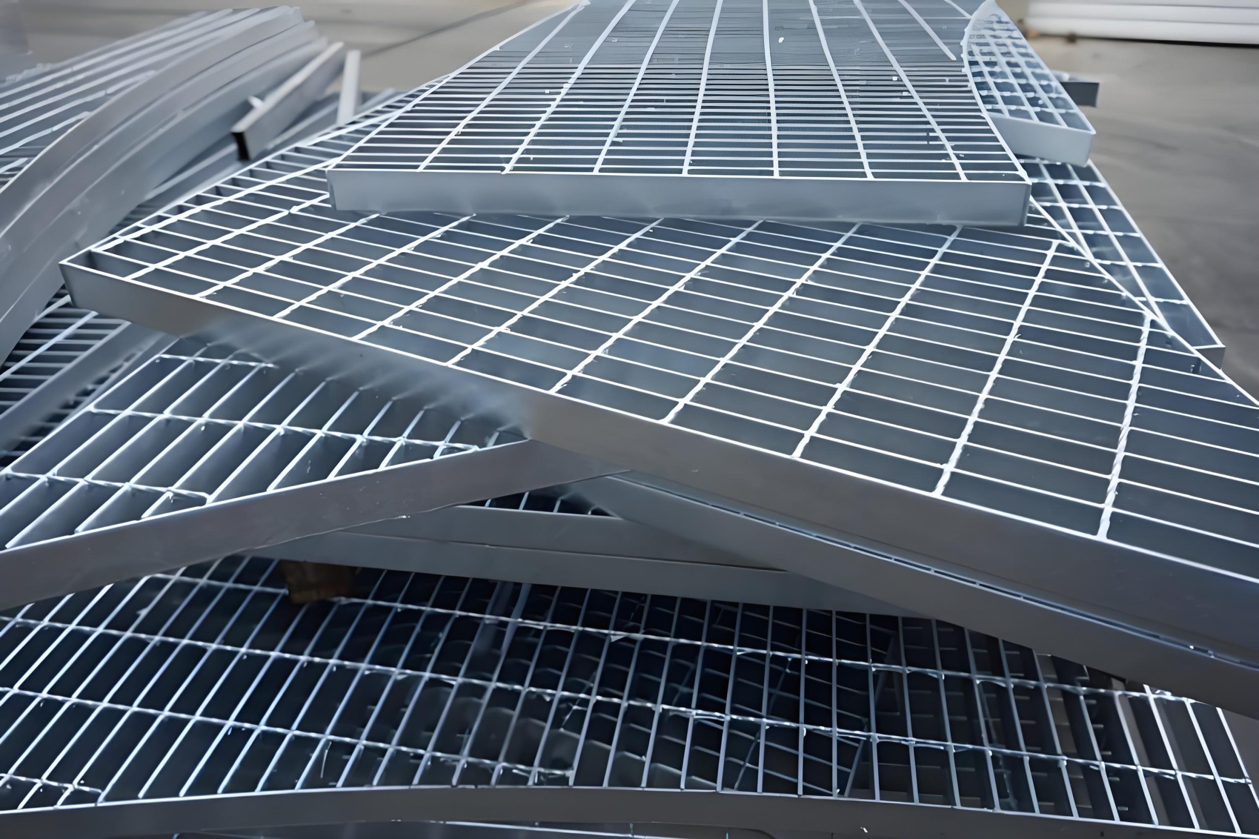
A metric specification may read:
Welded steel bar grating, 30 × 3 mm bearing bars, 30/100 mm mesh, serrated, hot-dip galvanized, 1000 × 6000 mm.
This means the bearing bars are 30 mm deep and 3 mm thick, spaced at 30 mm centers, with cross bars at 100 mm centers.
SurfacePlain, serrated, grooved, or applied grit
| Specification Item | Example |
|---|---|
| Construction type | Welded, pressure-locked, swage-locked, or riveted |
| Bearing bar size | 30 × 3 mm or 1-1/4 × 3/16 in |
| Bearing bar spacing | 30 mm or 19 space |
| Cross bar spacing | 100 mm or 4 in |
| Material | Carbon steel, galvanized steel, aluminum, stainless steel |
| Finish | Mill finish, painted, powder coated, hot-dip galvanized |
| Panel size | 1000 × 6000 mm or 36 × 240 in |
| Fabrication | Banding, cutouts, toe plates, clips, holes, frames |
Open area is the percentage of the panel surface that is open rather than occupied by metal. It affects drainage, ventilation, light transmission, debris passage, wind resistance, and weight.
A more open mesh pattern usually provides better drainage and lower weight. However, larger openings may be unsuitable where small tools, bolts, heels, or debris must be controlled.
A representative 19-W-4 galvanized steel bar grating product with 3/4 × 3/16 inch bearing bars, 1-3/16 inch bearing bar spacing, and 4 inch cross bar spacing is listed with approximately 77% open area. Open area changes when bar thickness, cross bar size, spacing, or construction type changes.
Bar grating is widely used where drainage matters, including outdoor walkways, industrial platforms, water treatment facilities, drainage channels, trench covers, stairs, balconies, and catwalks.
Good drainage depends on more than the grating opening. The supporting structure should avoid trapped water, drains should remain clear, and cutout edges should be properly finished to prevent debris accumulation.
High open area can allow tools, bolts, and loose materials to fall to lower levels. In areas with people or equipment below, the project may require toe plates, screens, close mesh grating, secondary mesh, or other falling-object protection.
Bar grating weight is normally expressed in kilograms per square meter or pounds per square foot. The exact weight depends on bearing bar dimensions, spacing, cross bar construction, material density, edge banding, serration, and finish.
The following table gives preliminary estimates for rectangular carbon steel bearing bars at approximately 30 mm bearing bar spacing and 100 mm cross bar spacing. Actual manufacturer weight can vary depending on cross bar size, welding method, serration, edge banding, and bar tolerances.
| Bearing Bar Size | Estimated Grating Body Weight | Typical Use |
|---|---|---|
| 25 × 3 mm | Approximately 22–24 kg/m² | Light to standard-duty industrial access |
| 30 × 3 mm | Approximately 26–28 kg/m² | General industrial walkways and platforms |
| 32 × 3 mm | Approximately 28–30 kg/m² | Standard metric industrial flooring |
| 40 × 3 mm | Approximately 34–37 kg/m² | Longer spans and medium-duty service |
| 25 × 5 mm | Approximately 35–38 kg/m² | Medium-duty short spans |
| 30 × 5 mm | Approximately 42–45 kg/m² | Higher-load industrial platforms |
| 40 × 5 mm | Approximately 55–58 kg/m² | Heavy-duty or long-span applications |
316 stainless steelSlightly heavier than carbon steelActual weight depends on grade and product geometry
| Material | Weight Comparison | Important Note |
|---|---|---|
| Carbon steel | Reference weight | Typical density approximately 7850 kg/m³ |
| Hot-dip galvanized steel | Slightly heavier than black steel | Zinc coating adds finished weight |
| 304 stainless steel | Slightly heavier than carbon steel | Density is typically close to 8000 kg/m³ |
| Aluminum | Much lighter for the same volume | Aluminum grating uses different bar profiles and should use aluminum-specific weight data |
Finished panel weight must include edge banding, toe plates, frames, cutout reinforcement, clips, bolts, handles, and permanent accessories. For freight, lifting, and structural design, request the final fabricated weight from the supplier.
Bar grating load capacity depends on the bearing bar size, bearing bar spacing, material, surface type, support span, load type, and permitted deflection. A bar grating that works for a pedestrian platform may not be suitable for a trench cover, vehicle wheel load, forklift route, or equipment platform.
Uniform load is spread across a large area. Concentrated load is applied over a small area, such as a person’s foot, tool, wheel, equipment leg, or maintenance cart. Concentrated loads often control grating selection because they create higher local stress.
Clear span is the unsupported distance between grating supports in the bearing bar direction. Increasing the span can significantly increase stress and deflection.
When the span is longer than the recommended value for a given bar size, the solution may include deeper bearing bars, thicker bars, closer supports, heavier-duty grating, or a redesigned support frame.
Grating must meet both strength and deflection requirements. A panel may not fail structurally but can still feel unstable or uncomfortable if deflection is too high.
Load tables should match the exact product construction, material, bearing bar size, span, and surface. For heavy-duty or vehicle applications, the wheel load, contact area, impact factor, support arrangement, and traffic frequency should be reviewed by the project engineer.
Heavy-duty grating may use thicker bearing bars, larger cross bars, heavier edge framing, and special welding. It is commonly selected for truck traffic, forklifts, loading areas, drainage covers, docks, and high-concentrated-load applications.
Heavy-duty grating should not be selected only by increasing panel thickness. The entire load path, including support angles, trench frames, welds, clips, and concrete or steel supports, must be checked.
Walkway grating should be selected according to the support span, traffic, exposure, drainage requirement, and safety conditions. General pedestrian access may use standard-duty grating, while wet or outdoor walkways may need serrated surfaces and galvanized steel.
| Walkway Condition | Typical Grating Direction |
|---|---|
| Dry indoor maintenance route | Plain standard-duty grating may be suitable |
| Outdoor walkway | Galvanized and serrated grating is often preferred |
| Wet processing area | Close mesh or serrated surface may be required |
| Food or washdown area | Stainless steel or aluminum may be considered |
| Coastal or chemical exposure | Material and finish should be selected for the actual environment |
| Public pedestrian route | Opening size, footwear, accessibility, and local codes require review |
For standard industrial walkways, 30/100 mm grating with 30 × 3 mm bearing bars is a common starting point. It is not a universal solution. The actual span and load may require a lighter or heavier configuration.
Platforms and mezzanines often use larger grating panels than narrow walkways. The grating may include handrail posts, toe plates, removable access panels, equipment cutouts, cable penetrations, and support beams at regular spacing.
For platforms, confirm the maximum clear span between support beams, expected maintenance loads, equipment loads, and required open area. If tools or small components may fall through, close mesh grating, toe plates, screens, or other protective measures may be needed.
Mezzanines may require more than standard pedestrian loading. Storage, maintenance carts, workers carrying materials, and vibration from equipment can affect the required grating size. The support frame and grating panels should be designed together.
Removable panels should be sized for safe handling. Large panels may reduce the number of joints, but they can become difficult to remove without lifting equipment. Handles, clips, safety chains, and panel labels may be useful for maintenance access.
Trench covers and drainage grates need special attention because the load is often applied over a narrow span with concentrated wheel, pedestrian, or equipment loads. The grate must also fit the trench frame accurately and provide enough bearing area at both ends.
Pedestrian trench covers may use standard-duty bar grating when the trench opening is narrow and support conditions are suitable. The mesh size should be selected to prevent unsafe openings while still allowing water to drain.
Vehicle and forklift traffic can require heavy-duty grating with deeper bearing bars, thicker sections, stronger cross bars, heavy frames, and carefully designed support angles. Wheel load, tire contact area, impact, axle load, and traffic frequency all affect the final selection.
Drainage channel grates may use open mesh for fast water flow or close mesh for smaller opening control. The correct pattern depends on debris size, cleaning method, pedestrian safety, water flow, and load requirement.
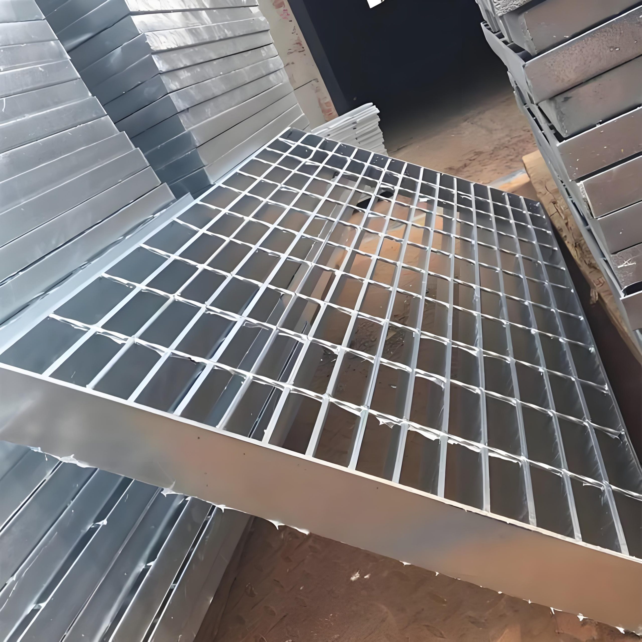
Custom fabrication is often necessary because real projects include columns, pipes, valves, drains, cable trays, equipment bases, handrail posts, and irregular support structures. A good shop drawing prevents incorrect field cutting and makes installation faster.
Edge banding closes the exposed ends of cut bearing bars. It improves appearance, adds rigidity, protects against sharp edges, and helps maintain the intended load path around a cut panel.
Cutouts that interrupt bearing bars may need reinforcement. A large opening can change the structural behavior of the panel, so the supplier should review the drawing and add banding, framing, or support details where required.
MaterialCarbon steel, galvanized steel, aluminum, stainless steelBearing bar size30 × 3 mm or 1-1/4 × 3/16 inMesh pattern30/100 mm or 19-W-4SurfacePlain, serrated, grooved, or applied gritPanel dimensions1000 × 3000 mm or panel scheduleBearing bar directionBars span between supports at 1000 mm centersLoad requirementUniform load, concentrated load, wheel load, deflection limitFabricationCutouts, edge banding, toe plates, clips, holes, framesFinishMill finish, paint, powder coating, hot-dip galvanizing
| Required Information | Example |
|---|---|
| Grating type | Welded, pressure-locked, swage-locked, or riveted |
What does 19-W-4 bar grating mean?
19-W-4 means the bearing bars are spaced 1-3/16 inches on center, the grating construction is welded, and the cross bars are spaced 4 inches on center. The bearing bar height, thickness, material, surface, and panel dimensions must still be specified separately.
What is the most common bar grating size?
Common industrial metric grating includes 30 × 3 mm bearing bars with 30/100 mm mesh spacing. In North American systems, 19-W-4 is a widely used standard spacing pattern. The most suitable size still depends on span, load, material, open-area requirement, and surface condition.
How do I choose the right bar grating thickness?
Choose bar grating thickness by checking the bearing bar height, thickness, support span, uniform load, concentrated load, and permitted deflection. A manufacturer load table or engineering calculation should be used because a thicker-looking grate is not automatically suitable for a longer span or higher load.