
Grating stair treads are widely used on industrial stairs, access platforms, steel structures, offshore facilities, power plants, warehouses, and commercial service areas because they combine high strength, drainage, ventilation, and slip resistance. There is no single grating stair tread size or weight suitable for every project. Common tread lengths range from 600 to 1200 mm, typical depths range from 240 to 305 mm, and bearing bar heights commonly range from 25 to 50 mm. The actual weight depends on the tread dimensions, bearing bar size, bar spacing, cross bars, nosing, end plates, material, and surface treatment. Standards such as ANSI/NAAMM MBG 531, OSHA 29 CFR 1910.25, ISO 14122-3, BS 4592, DIN 24531-1, and AS 1657 may apply, depending on the country, application, and project specification.
A grating stair tread is a prefabricated step made from metal bar grating. The main load-carrying components are parallel bearing bars extending between the stair stringers. Cross bars connect the bearing bars and maintain their spacing. A nosing is normally fitted along the leading edge, while end plates or carrier plates are welded to both ends for bolted or welded installation.
Compared with solid steel steps, open grating stair treads allow rainwater, wash water, snow, mud, dust, and small debris to pass through. This reduces standing water and helps keep industrial stairways usable in outdoor or frequently cleaned environments. The open construction also lowers wind resistance and usually reduces dead load on the supporting stair structure.
A typical metal grating stair tread consists of the following parts:
Grating stair treads are commonly fabricated from welded steel grating, pressure-locked grating, swage-locked grating, or riveted grating. Welded carbon steel grating is the most frequently selected option for general industrial stairs. Pressure-locked grating is often chosen where a cleaner architectural appearance, closer spacing, or a particular opening pattern is required.
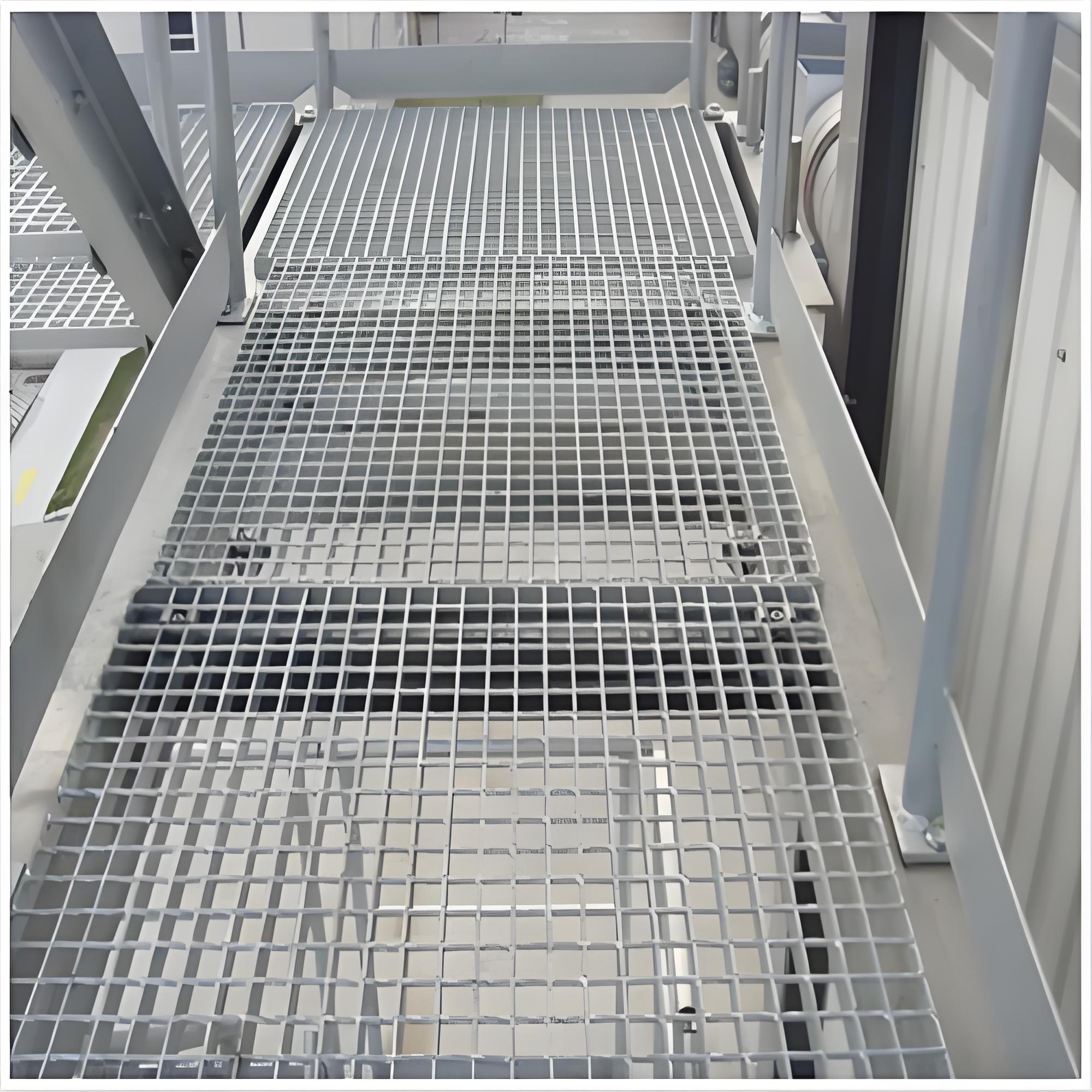
Dimension terminology can vary between manufacturers, so every purchase order should include a drawing. In this guide, tread length means the distance between the two tread ends and normally corresponds to the bearing-bar span between stringers. Tread depth means the front-to-back dimension in the direction of travel. Tread height means the height of the bearing bar.
| Dimension | Meaning | Typical Range | Primary Design Effect |
|---|---|---|---|
| Tread length or span | Distance from one end plate to the other | 600–1200 mm | Controls clear stair width and bending span |
| Tread depth | Front-to-back stepping surface | 240–305 mm | Controls foot space and stair geometry |
| Bearing bar height | Vertical depth of the load-carrying bar | 25–50 mm | Strongly affects load capacity and deflection |
| Bearing bar thickness | Thickness of each load-carrying bar | 3–6 mm | Affects strength, durability, and weight |
| Bearing bar pitch | Center-to-center distance between bearing bars | 25–40 mm | Affects open area, weight, load distribution, and opening size |
| Cross bar pitch | Center-to-center distance between cross bars | 50 or 100 mm | Affects stability, opening pattern, and local load distribution |
The bearing bars normally run in the length or span direction. They must be supported at both ends. A tread should never be installed with the bearing bars running parallel to the stringers unless the product has been specifically engineered for a different support arrangement.
Grating stair treads are manufactured in both metric and imperial dimensions. The word “standard” usually means a frequently produced factory size, not a universal dimension required by every regulation. Stair geometry, clear width, design load, support position, and local codes must be checked before selecting a stock tread.
Common metric tread lengths include 600, 700, 750, 800, 900, 1000, 1100, and 1200 mm. Common depths include 240, 250, 270, 280, 300, and 305 mm. Custom dimensions can be fabricated when the project requires a different stringer spacing or tread depth.
| Common Metric Tread Size | Typical Application | Selection Notes |
|---|---|---|
| 600 × 240 mm | Narrow maintenance stairs and compact equipment access | Check minimum clear stair width required by the applicable code |
| 700 × 240 mm | Machine access and light industrial stairs | Useful where installation space is limited |
| 800 × 240 mm | General industrial access stairs | A common compact factory size |
| 900 × 240 mm | Industrial platforms and service stairs | Provides more comfortable clear width |
| 1000 × 240 mm | Plant access and frequently used service stairs | Longer span may require a deeper bearing bar |
| 800 × 270 mm | General industrial stairways | Good balance between tread depth and overall stair run |
| 900 × 270 mm | Factories, warehouses, and processing facilities | Frequently specified with 30 × 3 mm or larger bearing bars |
| 1000 × 270 mm | Regular personnel access | Load and deflection should be verified for the full span |
| 1200 × 270 mm | Wide industrial stairs | Often requires deeper or thicker bearing bars |
| 800 × 300 mm | Stairs requiring a larger stepping surface | Confirm whether the stated depth includes the nosing |
| 1000 × 300 mm | Comfortable general-access stairways | Suitable for many heavy-use installations when correctly engineered |
| 1200 × 300 mm | Wide access stairs and major industrial routes | May require heavy-duty grating or an intermediate support |
North American manufacturers frequently offer tread depths related to the number and spacing of bearing bars. Typical nominal depths include approximately 9-3/4 inches, 10-15/16 inches, and 12-1/8 inches. Common lengths include 24, 30, 36, 42, and 48 inches, although longer custom treads are available.
| Imperial Size | Approximate Metric Size | Typical Use |
|---|---|---|
| 24 × 9-3/4 in | 610 × 248 mm | Compact maintenance access |
| 30 × 9-3/4 in | 762 × 248 mm | Narrow industrial stairs |
| 36 × 9-3/4 in | 914 × 248 mm | General industrial stairways |
| 42 × 10-15/16 in | 1067 × 278 mm | Wider service stairs |
| 48 × 12-1/8 in | 1219 × 308 mm | Wide stairs with a deeper stepping surface |
Imperial and metric dimensions should not be mixed casually. A nominal metric substitute may not match existing stringer holes or the required stair geometry. For replacement treads, measure the actual overall length, depth, end-plate height, hole diameter, slot dimensions, and hole centers.
The tread length is usually the bearing-bar span and is one of the most important structural dimensions. Increasing the length increases the clear stair width, but it also increases bending stress and deflection. A 30 × 3 mm bearing bar that performs adequately over a short span may not be suitable for a 1000 or 1200 mm span under the same load.
Before choosing the length, distinguish between the following measurements:
The overall tread length is often slightly smaller than the clear distance between stringers so the tread can be installed without interference. The required installation clearance depends on the fabrication method, coating thickness, tolerances, and fixing arrangement. It should be shown on the approved shop drawing rather than assumed.
Tread depth controls the usable stepping surface and affects the total horizontal run of the stair. Common industrial grating tread depths are 240, 250, 270, 280, 300, and 305 mm. In imperial systems, depths close to 9-3/4, 10-15/16, and 12-1/8 inches are frequently available.
The specified grating depth is not always identical to the code-defined tread depth. Some regulations measure tread depth horizontally between the leading edges of adjacent steps. A projecting, rounded, or steeply sloped nosing may not be fully counted as usable tread depth. For example, OSHA has clarified how the tread-depth measurement applies to standard stairs. The complete stair geometry must therefore be reviewed, not only the front-to-back dimension printed in a grating catalog.
Common bearing bar heights include 25, 30, 32, 35, 40, 45, and 50 mm. Imperial alternatives commonly include 1, 1-1/4, 1-1/2, 1-3/4, and 2 inches. Higher bars provide greater bending resistance and normally allow a longer span or higher load, provided the supporting connections and material strength are also adequate.
| Bearing Bar Size | Typical Classification | Common Use |
|---|---|---|
| 25 × 3 mm | Light to standard duty | Short-span maintenance treads with controlled loading |
| 30 × 3 mm | Standard duty | General industrial stair treads |
| 32 × 3 mm | Standard duty | Metric alternative for general access stairs |
| 40 × 3 mm | Medium duty | Longer spans or more restrictive deflection limits |
| 25 × 5 mm | Medium duty | Short spans requiring a thicker, more durable bar |
| 30 × 5 mm | Medium to heavy duty | High-traffic or higher-load industrial stairs |
| 40 × 5 mm | Heavy duty | Longer spans and demanding service conditions |
| 50 × 5 mm or larger | Heavy duty | Special high-load applications subject to engineering verification |
Bar height generally has a stronger effect on bending stiffness than a similar increase in bar thickness. However, thickness improves section capacity, corrosion allowance, impact resistance, and durability at welded connections. The most economical selection is made from a verified load table rather than by comparing bar height alone.
Bearing bars carry the tread load to the stringers. Their height, thickness, spacing, material strength, surface profile, and span must all be stated when a grating stair tread is ordered.
Standard industrial treads frequently use bearing bars 3, 4, 4.5, 5, or 6 mm thick. In North American specifications, 1/8, 3/16, and 1/4 inch thicknesses are common. A 3 mm or 1/8 inch bar may be appropriate for standard-duty access, while thicker bars are selected for high traffic, severe corrosion, heavy loads, or long service life.
Bearing bar pitch is measured from the center of one bearing bar to the center of the next. Frequently supplied metric pitches include 25, 30, 30.16, 34.3, and 40 mm. Common imperial spacing designations include 19, 15, and 11 space patterns.
| Spacing Description | Approximate Center-to-Center Pitch | General Characteristics |
|---|---|---|
| 25 mm pitch | 25 mm | Closer spacing, smaller openings, higher weight, and more bearing bars |
| 30 mm pitch | 30 mm | Widely used metric industrial grating pattern |
| 30.16 mm pitch | 1-3/16 in | Common North American 19-space pattern |
| 34.3 mm pitch | Approximately 1.35 in | Common in some pressure-locked and regional grating systems |
| 40 mm pitch | 40 mm | Lighter open pattern where opening size and local loads permit |
| 15-space pattern | 15/16 in or approximately 23.8 mm | Closer spacing than the 19-space pattern |
| 11-space pattern | 11/16 in or approximately 17.5 mm | Close-mesh pattern for smaller openings and special requirements |
Reducing the bearing bar pitch places more load-carrying bars in the tread. This usually increases the weight and can improve the distribution of concentrated loads. It also reduces the clear opening between adjacent bars. The final capacity must still come from the manufacturer’s load data because the bearing bar profile, material strength, fabrication method, and serration can affect performance.
In a common North American designation such as 19-W-4, the first number identifies the bearing bar spacing series, the letter “W” identifies welded construction, and the final number identifies the cross bar spacing series. A 19-W-4 tread normally has bearing bars spaced 1-3/16 inches on center and cross bars spaced 4 inches on center.
The designation 19-W-4 does not state the bearing bar height or thickness. A complete description must also include a bar size, such as 1-1/4 × 3/16 inches. Surface type, material, nosing, finish, and tread dimensions must be added separately.
Cross bars connect the bearing bars, preserve the opening pattern, and distribute local forces. They are not normally the primary members spanning between the stringers. Common cross bar forms include twisted square bars, round bars, flat bars, and bars mechanically locked into the bearing bars.
Welded steel grating commonly uses twisted square cross bars resistance-welded to the bearing bars. This creates a rigid panel that can be cut into stair tread sizes and fitted with nosing and end plates. Common metric cross bar spacing is 50 or 100 mm, while common imperial spacing is 2 or 4 inches.
Pressure-locked grating uses rectangular cross bars pressed into pre-punched or slotted bearing bars under high pressure. It provides straight lines and a uniform architectural appearance. The process can also accommodate closer spacing and special visual patterns.
Swage-locked grating commonly uses tubular or round cross bars inserted through pre-punched bearing bars and mechanically deformed to lock the assembly. It is often associated with aluminum grating, although product construction varies by manufacturer.
| Cross Bar Pitch | Typical Description | Selection Considerations |
|---|---|---|
| 50 mm | Close cross bar spacing | More cross bars, smaller openings, higher unit weight, and improved local stability |
| 100 mm | Standard open spacing | Common for general industrial welded grating |
| 2 in | Close imperial spacing | Often identified by a “2” cross bar spacing series |
| 4 in | Standard imperial spacing | Common in 19-W-4 welded grating |
The opening size should be checked against the project’s safety requirements, dropped-object controls, footwear conditions, and any rules concerning the passage of objects. Close-mesh grating may be required where smaller openings are specified, but close spacing alone does not make an industrial stair an accessible route.
The most accurate tread weight is obtained from the approved fabrication drawing or the manufacturer’s finished product data. A complete tread includes more than the rectangular grating area, so multiplying panel weight by tread area alone will normally underestimate the shipping weight.
A practical estimating formula is:
Finished tread weight = grating body weight + nosing weight + two end-plate weights + fastened accessories + coating allowance
When the manufacturer provides grating mass per square meter, the body weight can be calculated as:
Grating body weight (kg) = tread length (m) × tread depth (m) × grating unit mass (kg/m²)
The nosing weight can be calculated as:
Nosing weight (kg) = tread length (m) × nosing linear mass (kg/m)
For rectangular end plates:
End-plate weight (kg) = 2 × plate length (m) × plate height (m) × plate thickness (m) × material density (kg/m³)
The volume removed by bolt holes is small and is normally ignored during preliminary estimating. It can be deducted when a highly accurate weight is required.
If a unit weight is not available, the bearing bars and cross bars can be estimated separately. For steel grating with rectangular bearing bars, the approximate bearing-bar mass per square meter is:
Bearing-bar mass (kg/m²) = 7.85 × bearing bar height (mm) × bearing bar thickness (mm) ÷ bearing bar pitch (mm)
This formula uses a nominal steel density of 7850 kg/m³. Cross bars, weld metal, edge bars, nosing, and end plates must then be added.
For example, a 30 × 3 mm bearing bar at 30 mm pitch has an approximate bearing-bar mass of:
7.85 × 30 × 3 ÷ 30 = 23.55 kg/m²
If approximately 2.8 kg/m² is allowed for 6 mm cross bars at 100 mm pitch, the estimated grating body mass becomes approximately 26.4 kg/m² before adding the nosing and end plates.
Consider a carbon steel stair tread with these nominal specifications:
Grating body: 0.800 × 0.270 × 26.4 = 5.70 kg
Nosing: 0.800 × 1.8 = 1.44 kg
End plates: 2 × 0.270 × 0.065 × 0.003 × 7850 = 0.83 kg
Estimated unfinished tread weight: 5.70 + 1.44 + 0.83 = 7.97 kg
The practical estimate is therefore approximately 8.0 kg before allowing for coating variation, welding, dimensional tolerances, and any special fixing components. Hot-dip galvanizing adds zinc to the surface and normally increases the finished weight by several percent. The exact increase varies with coating thickness, drainage, surface area, and fabrication details.
| Material | Typical Density | Weight Calculation Note |
|---|---|---|
| Carbon steel | Approximately 7850 kg/m³ | Common reference density for fabricated steel grating |
| Galvanized carbon steel | Steel base plus zinc coating | Use the carbon steel weight and add the actual or estimated coating mass |
| 304 stainless steel | Approximately 7930–8000 kg/m³ | Slightly heavier than carbon steel for identical geometry |
| 316 stainless steel | Approximately 7980–8000 kg/m³ | Actual density depends on the specified grade and product standard |
Density values are suitable for estimating but should not replace certified shipping weights. Finished weight can vary because bar tolerances, serration, welds, nosing profiles, end-plate dimensions, and zinc coating mass differ among factories.
The following chart provides preliminary estimates for carbon steel stair treads made with 30 × 3 mm bearing bars at 30 mm pitch, cross bars at approximately 100 mm pitch, a grating body mass of about 26.4 kg/m², a steel nosing mass of about 1.8 kg/m, and two 3 mm thick end plates approximately 65 mm high. The table is intended for budgeting, handling, and freight estimates. It is not a certified product weight chart.
| Tread Length × Depth | Estimated Uncoated Weight | Approximate Weight in Pounds | Typical Size Category |
|---|---|---|---|
| 600 × 240 mm | 5.6 kg | 12.3 lb | Compact |
| 700 × 240 mm | 6.4 kg | 14.1 lb | Compact |
| 800 × 240 mm | 7.2 kg | 15.9 lb | Standard |
| 900 × 240 mm | 8.1 kg | 17.9 lb | Standard |
| 1000 × 240 mm | 8.9 kg | 19.6 lb | Standard wide |
| 600 × 270 mm | 6.2 kg | 13.7 lb | Compact deep |
| 700 × 270 mm | 7.1 kg | 15.7 lb | Standard |
| 800 × 270 mm | 8.0 kg | 17.6 lb | Standard |
| 900 × 270 mm | 8.9 kg | 19.6 lb | Standard |
| 1000 × 270 mm | 9.8 kg | 21.6 lb | Standard wide |
| 1200 × 270 mm | 11.5 kg | 25.4 lb | Wide |
| 800 × 300 mm | 8.7 kg | 19.2 lb | Deep tread |
| 900 × 300 mm | 9.7 kg | 21.4 lb | Deep tread |
| 1000 × 300 mm | 10.6 kg | 23.4 lb | Wide and deep |
| 1200 × 300 mm | 12.6 kg | 27.8 lb | Wide and deep |
A tread made with 40 × 5 mm bearing bars will be considerably heavier than the values in this table. A tread with 40 mm bearing bar spacing may be lighter, while a close-mesh tread with 25 mm or smaller spacing will normally be heavier. Stainless steel treads of identical geometry are usually slightly heavier than uncoated carbon steel treads because of the difference in density.
The next table compares estimated steel grating body weights at 30 mm bearing bar pitch. An allowance of approximately 2.8 kg/m² has been included for cross bars. Nosing and end plates are not included.
| Bearing Bar Size | Estimated Bearing-Bar Mass | Estimated Grating Body Mass Including Cross Bars |
|---|---|---|
| 25 × 3 mm | 19.6 kg/m² | Approximately 22.4 kg/m² |
| 30 × 3 mm | 23.6 kg/m² | Approximately 26.4 kg/m² |
| 32 × 3 mm | 25.1 kg/m² | Approximately 27.9 kg/m² |
| 40 × 3 mm | 31.4 kg/m² | Approximately 34.2 kg/m² |
| 25 × 5 mm | 32.7 kg/m² | Approximately 35.5 kg/m² |
| 30 × 5 mm | 39.3 kg/m² | Approximately 42.1 kg/m² |
| 40 × 5 mm | 52.3 kg/m² | Approximately 55.1 kg/m² |
These calculated values are useful for comparing configurations, but a quotation should use the factory’s actual unit weight. Cross bar dimensions and manufacturing methods can produce a noticeable difference between two gratings with the same bearing bar size.
The required bearing bar size cannot be selected from tread weight alone. A heavier tread may have greater capacity, but capacity also depends on bar orientation, clear span, steel grade, spacing, support condition, concentrated load position, connection design, and the permitted deflection.
Concentrated loads often govern stair tread selection because a person’s weight is applied over a relatively small contact area. A load table for flooring panels should not automatically be used for stair treads without checking the tread-specific span, nosing, end plates, and connection details.
A deeper bearing bar has a much higher bending stiffness than a shallow bar of the same thickness. Conversely, increasing the unsupported span can rapidly increase stress and deflection. For this reason, a small increase in stair width may require a change from 30 × 3 mm to 40 × 3 mm, 30 × 5 mm, or another verified section.
When a tread is too flexible, it can feel unsafe even if the calculated stress remains below the material limit. The design must therefore satisfy both strength and serviceability criteria. Excessive deflection can also loosen fasteners, damage coatings near connections, and make the nosing feel unstable.
The bearing bars should have adequate end support on the end plates or stringer arrangement. End plates must be properly welded to the grating and designed to transfer the applied load into the stair stringers. Bolts, slots, washers, and supporting holes must have sufficient edge distance and bearing area.
A long tread should not be assumed to gain support from a center member unless that member is shown on the structural drawing and the tread is detailed to bear on it. If an intermediate support is used, its height and position should prevent rocking and should not create an unexpected high point.
For applicable workplaces in the United States, OSHA 29 CFR 1910.25 provides requirements for stairways. Among its general provisions, each stair must support at least five times the normal anticipated live load and not less than a concentrated load of 1,000 pounds applied at any point. For standard stairs covered by the rule, OSHA also specifies requirements including stair angle, tread depth, riser height, and minimum width.
These requirements apply to the stair system within the stated scope of the regulation. They do not mean that every stock grating tread is automatically “OSHA approved.” Compliance depends on the installed stair geometry, structural capacity, handrails, landings, uniformity, clearances, and other conditions.
OSHA’s standard-stair provisions generally require an angle between 30 and 50 degrees, a maximum riser height of 9.5 inches, a minimum tread depth of 9.5 inches, and a minimum width of 22 inches between vertical barriers, subject to the rule’s scope and stated exceptions. A competent designer should verify the exact provisions applicable to new, existing, general-industry, construction, ship-stair, or special access arrangements.
Uncoated carbon steel is economical and easy to weld. It is suitable for dry indoor environments or for projects where the complete stair will receive a specified paint or coating system after fabrication. Mill-finish carbon steel will develop rust when exposed to moisture, so it should not be treated as a corrosion-resistant finish.
Carbon steel is often chosen when:
Hot-dip galvanized steel is the most common choice for outdoor industrial stairs. The tread is normally fabricated first and then immersed in molten zinc so the bearing bars, cross bars, nosing, end plates, and weld areas receive a protective coating.
Relevant coating specifications may include ISO 1461:2022 or ASTM A123/A123M-24, depending on the contract and region. Fasteners may be covered by a different coating standard, so the tread coating and hardware coating should be specified separately.
Galvanized steel is commonly selected for:
Drainage and venting details are important during galvanizing. Poorly detailed closed spaces can create processing hazards, while trapped zinc can cause an uneven finish or unnecessary weight. All welding, drilling, and cutting should preferably be completed before galvanizing. If field cutting is unavoidable, the damaged coating should be repaired using the specified approved method.
Stainless steel grating stair treads are used where corrosion resistance, hygiene, appearance, or long service life justifies the higher initial cost. Type 304 is common in food processing, architectural interiors, and many general corrosive environments. Type 316 contains molybdenum and normally provides better resistance in chloride-containing, coastal, and more aggressive industrial environments.
Stainless steel is often selected for:
The term “stainless steel” is not a complete material specification. The order should identify the grade, applicable material standard, surface finish, welding requirements, and any pickling or passivation treatment. Stainless fasteners should also be checked for compatibility with the tread and supporting stringers.
| Material | Corrosion Resistance | Relative Initial Cost | Typical Environment | Important Notes |
|---|---|---|---|---|
| Uncoated carbon steel | Low without an added coating | Low | Dry indoor areas | Usually painted or coated when exposed to moisture |
| Hot-dip galvanized steel | Good for many outdoor environments | Medium | Outdoor industrial and general infrastructure | Confirm coating standard, finish, and repair requirements |
| 304 stainless steel | Good in many hygienic and moderately corrosive areas | High | Food plants, interiors, and washdown areas | Not the preferred grade for every chloride exposure |
| 316 stainless steel | Higher resistance in many chloride and chemical environments | Higher | Coastal, marine, and chemical facilities | Grade selection still requires an environmental review |
Plain grating uses bearing bars with smooth top edges. It is economical, easy to clean, and suitable for dry areas where additional slip resistance is not required. Plain treads should still have a suitable nosing because the leading edge is a critical foot-contact area.
Serrated bearing bars have notches cut or formed into their top edges. These notches provide additional contact edges and can improve traction where water, oil, mud, ice, or process residue may be present.
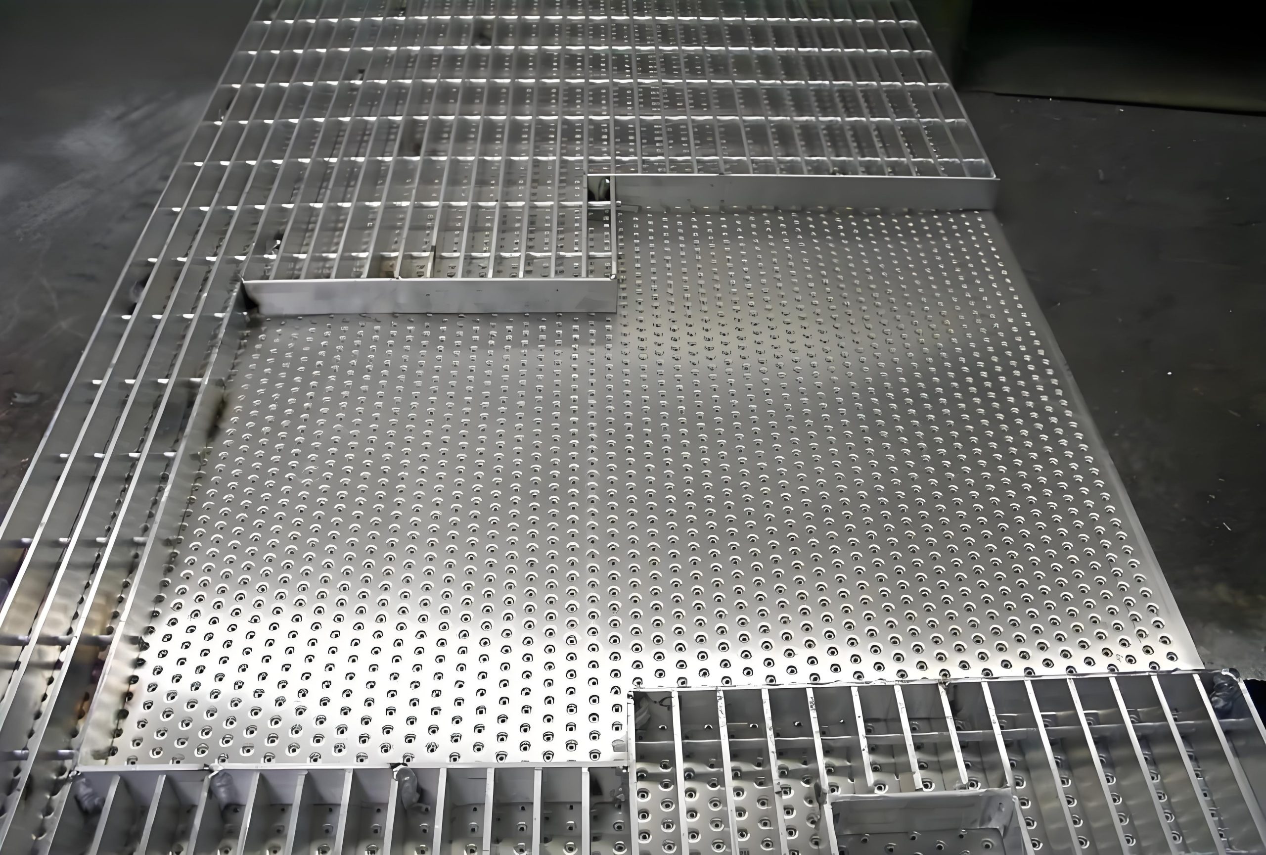
Serration does not eliminate slip risk. Performance depends on the contaminant, footwear, walking direction, notch pattern, nosing, drainage, and maintenance. Because serrations alter the top portion of the bearing bar, serrated grating should be checked using the manufacturer’s corresponding load table rather than a plain-bar table.
Additional anti-slip treatment is often concentrated at the nosing because this is where the user places the front of the foot. Options include checkered plate nosing, abrasive grit nosing, perforated nosing, cast abrasive strips, and replaceable anti-slip inserts.
| Surface Type | Suitable Conditions | Advantages | Limitations |
|---|---|---|---|
| Plain bearing bars | Dry, clean indoor areas | Economical and easy to clean | Less traction when contaminated |
| Serrated bearing bars | Wet, oily, muddy, or outdoor areas | More contact edges across the tread | Can retain some debris and requires a serrated load rating |
| Checkered plate nosing | General industrial use | Durable, visible leading edge | Raised pattern alone may not suit severe contamination |
| Abrasive nosing | High slip-risk areas | High initial traction | Abrasive layer can wear and may require replacement |
| Perforated or toothed nosing | Mud, snow, and demanding outdoor service | Aggressive edge and drainage | Footwear and cleaning requirements should be reviewed |
The correct surface should be selected from a slip-risk assessment. A heavily serrated surface is not automatically the best choice for every facility. Barefoot areas, hygienic plants, public stairs, and sites using soft footwear may require different surface details.
Nosing strengthens the front edge, makes the leading edge easier to identify, and provides a more consistent foot-contact surface. It also protects the first bearing bar from repeated impacts.
A checkered plate bent to form a 90-degree angle is widely used on steel grating treads. Typical leg dimensions may be approximately 30 to 50 mm, with thickness commonly around 3 to 5 mm. Imperial products may use unequal legs such as 1-1/4 × 1-3/4 inches. Dimensions vary with the tread depth, bearing bar size, and manufacturer’s standard detail.
A plain steel angle provides a strong leading edge but offers less surface texture than checkered or abrasive nosing. It may be suitable where the stair is dry or where a separate anti-slip strip will be fitted.
Abrasive nosing incorporates mineral grit, aluminum oxide, or another high-friction material. It is used in areas where improved traction and visual contrast are important. The substrate, adhesive or bonding system, expected wear, temperature, and chemical exposure should be specified.
Perforated, punched, or toothed nosing allows contaminants to pass through and creates additional gripping edges. It is frequently considered for outdoor stairs exposed to rain, snow, mud, or loose material.
Contrasting nosing uses a different color or material to make each tread edge more visible. Yellow-painted steel, yellow abrasive strips, and contrasting metallic finishes are common. The required contrast and dimensions should be coordinated with the project’s accessibility, safety, and architectural requirements.
The nosing size must be coordinated with the grating depth and stair geometry. The supplier should clearly state whether the quoted tread depth is:
A large nosing projection should not be used to compensate for an inadequate stair run without confirming the applicable code. Some measurement rules exclude steeply sloped or rounded portions from usable tread depth.
End plates, also called carrier plates, close the tread ends and transfer loads from the bearing bars to the stair stringers. They also provide a flat surface for drilling or slotting mounting holes. End-plate height is usually greater than the bearing bar height so there is room for the fixing holes below or beside the grating body.
Common end-plate thicknesses include 3, 4, 5, and 6 mm. The correct thickness depends on tread length, load, hole geometry, material strength, connection type, and edge distance. Heavy-duty treads may require thicker plates or a specially reinforced connection.
Round holes provide a controlled fit when the stringer holes are accurately located. They are suitable for repetitive factory-fabricated stairs where the drilling pattern is consistent. Installation tolerances are smaller than with slots, so the hole centers must match the structural drawing.
Horizontal or vertical slots provide adjustment during installation. They can accommodate small differences in stringer spacing, hole position, or coating thickness. Slots should not be made unnecessarily long because the end plate still requires adequate net section, edge distance, and washer bearing area.
Bolted fixing is usually preferred where treads may need inspection, replacement, or removal. A typical assembly includes bolts, nuts, flat washers, and sometimes locking nuts or spring washers. The fastener grade, diameter, coating, tightening method, and corrosion compatibility should be specified.
Advantages of bolted treads include:
Welded attachment can provide a permanent connection, but it complicates replacement and may damage galvanized or painted finishes. When galvanized treads are field welded, the affected coating must be removed as required for welding and then repaired after the work. Welding procedures should account for material grade, coating, ventilation, distortion, and site safety.
Some stair designs use special clips, brackets, or captive fixings. These can reduce drilling or permit access from one side. Proprietary fixing systems should be installed in accordance with the supplier’s instructions and checked for vibration, loosening, and the required load transfer.
| Drawing Item | Required Information |
|---|---|
| Plate size | Length, height, thickness, and material grade |
| Hole or slot size | Diameter or full slot length and width |
| Hole centers | Horizontal and vertical distances from defined plate edges |
| Edge distance | Distance from opening to plate end and plate edge |
| Welds | Location, size, length, process, and any project-specific quality requirement |
| Nosing connection | Nosing profile and its attachment to the end plate and grating |
| Finish | Paint, galvanizing, passivation, or other treatment |
| Installation clearance | Relationship between overall tread length and clear stringer spacing |
Grating stair tread standards do not all cover the same subject. One document may address grating manufacture and load tables, another may regulate complete stair geometry, and another may specify galvanizing. A compliant project may therefore need several coordinated standards.
| Standard or Regulation | Region or Scope | Relevance to Grating Stair Treads |
|---|---|---|
| ANSI/NAAMM MBG 531-24 | North American metal bar grating practice | Technical data, specifications, load tables, and typical stair tread details for metal bar grating |
| ANSI/NAAMM MBG 534-24 | Metal bar grating engineering design | Design formulas and engineering procedures used for bar grating |
| NAAMM MBG 535-25 | Metal bar grating code of standard practice | Recommended industry practices for ordering, fabrication, and coordination |
| NAAMM MBG 533-21 | Grating fabrication welding | Welding practices for steel, stainless steel, and aluminum bar grating |
| OSHA 29 CFR 1910.25 | United States general-industry stairways within its scope | Stair load, width, depth, riser, angle, uniformity, and other installed-stair requirements |
| ISO 14122-3:2016 | Permanent means of access to machinery | Requirements for stairs, stepladders, and guardrails associated with machinery |
| BS 4592-1:2006 | United Kingdom industrial flooring and metal open bar gratings | Design, manufacture, supply, installation, and related requirements for metal open bar grating and stair treads |
| BS 4592-0:2006 | United Kingdom common requirements | General requirements coordinated with the material-specific parts of BS 4592 |
| DIN 24531-1:2006-04 | Germany, metal gratings used as stair treads | Dimensions, construction, fixing, permissible loading, and related requirements |
| AS 1657:2018 | Australia, fixed access systems | Design, selection, construction, and installation of fixed platforms, walkways, stairways, and ladders |
| ISO 1461:2022 | International galvanizing specification | Properties and test methods for hot-dip galvanized coatings on fabricated iron and steel articles |
| ASTM A123/A123M-24 | United States galvanizing specification | Hot-dip zinc coatings on fabricated iron and steel products |
The National Association of Architectural Metal Manufacturers publishes widely used metal bar grating manuals. ANSI/NAAMM MBG 531-24 contains technical information for standard metal bar grating and stair treads, while MBG 534-24 addresses engineering design procedures. Project specifications should identify the required grating type, bar size, spacing, loading, deflection, material, finish, and tread details rather than referring only to “NAAMM grating.”
OSHA regulations concern the safety of installed workplace stairs, not merely the manufacture of one grating component. Tread capacity, stair width, tread depth, riser height, stair angle, landings, handrails, and uniformity may all affect compliance. Construction-phase stairs can also fall under provisions different from permanent general-industry stairs.
ISO 14122-3 applies to non-powered stairs, stepladders, and guardrails that form part of permanent access to stationary machinery within the standard’s scope. The 2016 edition remains published, although the ISO record indicates revision activity. Projects should confirm the current edition and any national or regional adoption when the order is placed.
The BS 4592 series addresses industrial flooring and stair treads. BS 4592-1 covers metal open bar gratings, while BS 4592-0 contains common requirements. Where access to machinery is involved, BS EN ISO 14122 may also be relevant. The designer should determine the correct scope rather than selecting a standard solely because the project is located in the United Kingdom.
DIN 24531-1 specifically addresses metal gratings used as stair treads. It includes requirements related to dimensions, execution, fastening, and permissible loading. It is frequently referenced for European industrial stair tread orders, especially when standardized tread construction and fixing details are required.
AS 1657 is widely used for fixed platforms, walkways, stairways, and ladders in Australia. It covers the complete access arrangement rather than only the grating panel. The stair tread supplier therefore needs the project’s dimensions and loads, while the stair designer remains responsible for coordinating the full access system.
Standards are amended, reconfirmed, revised, or replaced over time. Contract documents may also require a specific historical edition. Before production, confirm:
Start by defining who will use the stair, how frequently it will be used, and what may be carried over it. A rarely used maintenance stair has different requirements from a main factory access route. Also identify whether the installation is indoors, outdoors, in a hygienic plant, near saltwater, or exposed to chemicals.
Determine the clear width, stringer spacing, stair angle, rise, run, tread depth, and required nosing projection. Check these dimensions against the applicable code before requesting the tread quotation. If the stair is replacing an existing structure, measure several tread positions because older stringers may not be perfectly uniform.
Provide the required uniform load, concentrated load, load contact area, load location, and deflection limit. If the project specification gives only a general floor load, ask the structural engineer whether a separate concentrated stair tread load applies.
Choose bearing bar height, thickness, and spacing from a verified manufacturer load table. Confirm that the load table applies to the correct material, plain or serrated surface, support span, and grating construction.
Use carbon steel for controlled dry environments or where a separate coating system will be applied. Select hot-dip galvanized steel for many outdoor industrial installations. Consider 304 or 316 stainless steel where hygiene, chemical exposure, coastal conditions, or long-term corrosion resistance requires it.
Plain grating may be sufficient in a dry interior. Serrated grating and an anti-slip nosing are more appropriate where water, oil, ice, or process material can reach the steps. Include visibility requirements if contrasting nosing is needed.
Provide the end-plate thickness, height, hole or slot dimensions, hole centers, and fastener specification. Do not rely on a generic factory drilling pattern when the stringer drawing already exists. A small hole-position error can delay installation across an entire stair flight.
Separate product standards from complete stair regulations and coating standards. A typical project may reference a NAAMM grating standard, an OSHA stair regulation, an ASTM galvanizing specification, and a structural design code. Each reference serves a different purpose.
Request the finished weight per tread when lifting, freight, manual handling, or structural dead load is important. The supplier’s final weight should include grating, nosing, end plates, coating, and permanent accessories.
The approved drawing should show the direction of the bearing bars, overall dimensions, grating pattern, nosing, end plates, holes, welds, finish, and installation orientation. Checking one representative drawing before mass production prevents repeated dimensional errors.
A clear order description may follow this format:
Hot-dip galvanized welded steel grating stair tread, 900 mm long × 270 mm deep, 30 × 3 mm bearing bars at 30 mm pitch, twisted cross bars at 100 mm pitch, serrated top surface, checkered angle nosing, 3 mm end plates with slotted bolt holes, fabricated and galvanized after welding, design load and deflection as shown on the approved project drawing.
For a complete inquiry, provide the following:
Two treads with the same overall dimensions can have very different weights and capacities. The bearing bar size, pitch, material, surface, nosing, and end plates must also be identified.
Manufacturers do not always use the words “width” and “length” in the same way. State the bearing-bar direction and provide a drawing so the load-carrying bars cannot be oriented incorrectly.
Panel weight excludes the nosing, end plates, welds, coating, and some accessories. These components can represent a meaningful portion of the total weight, particularly on short treads.
Serration depth, tooth shape, spacing, and manufacturing method vary. Ask for a sample or detailed drawing when slip resistance is critical, and use the correct serrated load table.
A projecting nosing does not automatically count toward the full code-defined tread depth. Coordinate the finished leading edge with the rise, run, and measurement method required by the applicable regulation.
The order should distinguish batch hot-dip galvanizing after fabrication from pre-galvanized material, zinc-rich paint, electroplating, or another zinc coating. State the applicable galvanizing standard and required inspection documents.
Legacy drawings may cite withdrawn editions. Check the standard’s current status and determine whether the contract requires the latest edition or the edition named in the original design.
Stock hole patterns may not match existing stairs. Measure the stringer holes or approve a coordinated drawing before production. For retrofit work, a template can be more reliable than dimensions taken from a single old tread.
What is the standard size of a grating stair tread?
There is no single universal size, but common metric grating stair treads are 600 to 1200 mm long and 240 to 305 mm deep. Frequently ordered sizes include 800 × 240 mm, 900 × 270 mm, 1000 × 270 mm, and 1000 × 300 mm. Common imperial depths include approximately 9-3/4, 10-15/16, and 12-1/8 inches. The correct size must match the stringer spacing, required clear stair width, stair geometry, load, and applicable standard.
How much does a steel grating stair tread weigh?
A standard steel grating stair tread commonly weighs approximately 5 to 13 kg, although heavy-duty and oversized treads can weigh considerably more. As a practical example, an 800 × 270 mm carbon steel tread made with 30 × 3 mm bearing bars at 30 mm pitch may weigh about 8 kg after including typical nosing and end plates but before exact coating adjustments. Finished weight should always be confirmed from the manufacturer’s drawing.
Which standard applies to grating stair treads?
The applicable standard depends on the project location and use. ANSI/NAAMM MBG 531 and MBG 534 are commonly used for metal bar grating in North America, while OSHA 29 CFR 1910.25 may apply to installed workplace stairs in the United States. ISO 14122-3 covers permanent access to machinery, BS 4592 addresses industrial flooring and stair treads in the United Kingdom, DIN 24531-1 covers metal grating stair treads in Germany, and AS 1657 applies to many fixed access systems in Australia. Galvanized products may additionally reference ISO 1461 or ASTM A123/A123M.
