
Steel Walkway Grating Standard Sizes | Panel Dimensions, Mesh & Span Guide
Steel walkway grating is supplied in many combinations of panel width, length, bearing bar size, mesh spacing, surface type, and edge treatment. There is no single dimension that fits every catwalk, platform, ramp, or maintenance walkway. The correct size depends on the clear span, load, support arrangement, opening safety, drainage requirements, and installation layout. This guide explains the most common steel walkway grating sizes and how to select a practical specification for an industrial or commercial project.
Standard steel walkway grating sizes normally describe three different aspects of the product:
A grating specification such as 30 × 5 mm, 30 × 100 mm may indicate a 30 mm-high, 5 mm-thick bearing bar with 30 mm bearing bar pitch and 100 mm cross bar pitch. The panel may then be supplied at 600 × 3,000 mm, 1,000 × 6,000 mm, or another finished size.
Panel dimensions and mesh dimensions should not be confused. A large panel can use a light bearing bar if it is supported at short intervals, while a narrow panel may still require a heavy bearing bar if its clear span is long or it carries concentrated loads.
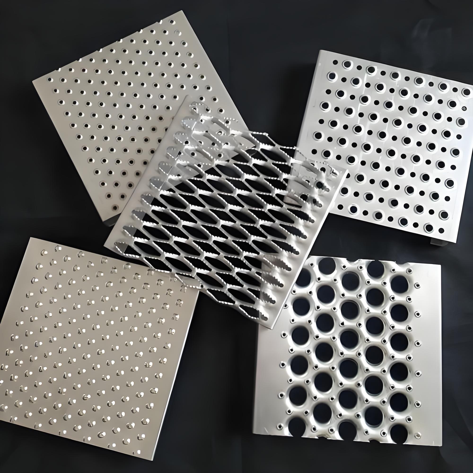
Factories often keep regular stock panels and produce standard lengths to reduce cutting and setup time. The actual stock range varies by country, welding machine, press-locking equipment, and export market.
| Common Width | Common Length | Typical Application |
|---|---|---|
| 300 mm | 1,000–3,000 mm | Narrow service strips, drainage edges, and access paths |
| 450 mm | 2,000–6,000 mm | Pipe rack maintenance routes and narrow catwalks |
| 600 mm | 2,000–6,000 mm | Single-person industrial walkways |
| 750 mm | 3,000–6,000 mm | Maintenance walkways and equipment access |
| 900 mm | 3,000–6,000 mm | Comfortable industrial access and platform sections |
| 1,000 mm | 3,000–6,000 mm | Common catwalk and factory platform panels |
| 1,200 mm | 3,000–6,000 mm | Wider platforms, ramps, and two-way maintenance traffic |
Common production lengths include 2,000, 3,000, 4,000, 5,000, 5,800, and 6,000 mm. Imperial stock may be close to 3 ft × 20 ft, 3 ft × 24 ft, 4 ft × 20 ft, or 4 ft × 24 ft. Metric and imperial sizes are not always interchangeable because the bearing bar layout, banding, and end cuts must be coordinated with the support structure.
Stock panels generally cost less than fully custom pieces. However, the cheapest panel is not always the best choice if it creates many field cuts, unsupported joints, or unnecessary waste.
Walkway width should be selected according to the number of people, maintenance activity, equipment movement, and access restrictions. A narrow route used only for occasional inspection has different requirements from a platform where workers carry tools or remove components.
| Walkway Width | Practical Use | Design Notes |
|---|---|---|
| 300–450 mm | Occasional inspection or narrow service access | Not normally suitable for carrying large tools or passing another person |
| 600 mm | Single-person industrial maintenance walkway | Common where space around pipes or equipment is limited |
| 750–900 mm | General plant access and maintenance routes | More comfortable for workers carrying hand tools |
| 1,000–1,200 mm | Platforms, ramps, and higher-traffic walkways | Allows easier movement and may accommodate carts or equipment |
| Above 1,200 mm | Large platforms or two-way traffic areas | May require additional support beams and intermediate panel joints |
Minimum clear width, guardrail space, toe-board position, and headroom may be controlled by the local building code, occupational safety rules, or project specification. The clear walking route should be measured after handrails, pipes, cable trays, columns, and other obstructions are installed.
Bearing bars are the primary load-carrying members. Their height and thickness have a direct effect on stiffness, weight, cost, and maximum span. Typical options include 25 × 3 mm, 25 × 5 mm, 30 × 3 mm, 30 × 5 mm, 32 × 5 mm, 40 × 5 mm, and 50 × 5 mm.
| Bearing Bar Example | General Position | Possible Use |
|---|---|---|
| 25 × 3 mm | Light-duty | Short-span indoor walkways and light access panels |
| 25 × 5 mm | Light to medium-duty | Short spans requiring more stiffness than 25 × 3 mm |
| 30 × 3 mm | Standard-duty | General industrial catwalks with moderate support spacing |
| 30 × 5 mm | Medium-duty | Longer spans or heavier maintenance loads |
| 32 × 5 mm | Medium to heavy-duty | Platforms, ramps, and service floors |
| 40 × 5 mm | Heavy-duty | Equipment areas, high traffic, and demanding spans |
| 50 × 5 mm | Very heavy-duty | Vehicle access, long spans, or high concentrated loads |
These categories are only preliminary guidance. A bearing bar that is adequate over a 600 mm clear span may be unsuitable over a 1,500 mm span. The factory load table must be based on the exact bearing bar dimensions, mesh, support spacing, load type, and allowable deflection.
For a preliminary selection, short-span walkways may begin with 25 or 30 mm bars, while longer or more heavily loaded platforms may require 32, 40, or 50 mm bars. Intermediate support beams can sometimes reduce the required bar size more economically than upgrading every panel to a heavy-duty specification.
Bearing bar pitch is the center-to-center distance between adjacent bearing bars. It is not the same as the clear opening. The clear opening is smaller because part of the pitch is occupied by the bearing bar thickness.
| Bearing Bar Pitch | General Characteristics | Typical Selection |
|---|---|---|
| 19 mm | Close mesh with small openings | Pedestrian safety, small wheels, tools, and debris retention |
| 25 mm | Relatively close mesh with balanced drainage | Industrial walkways and platforms needing smaller openings |
| 30 mm | Common general-purpose spacing | Catwalks, platforms, ramps, and maintenance access |
| 40 mm | More open and lighter for the same bar size | Drainage, ventilation, and areas without small-wheel concerns |
Closer pitch normally means more bearing bars per meter, which increases steel consumption and weight. It can also improve heel safety and support for small wheels. Wider pitch reduces weight and may improve open area, but the clear opening must still meet the project’s safety requirements.
Cross bars hold the bearing bars in position and help distribute local loads. Common cross bar spacings are 50, 75, and 100 mm, measured center-to-center.
| Cross Bar Spacing | Effect on the Panel | Typical Application |
|---|---|---|
| 50 mm | Closer visual pattern and improved small-object retention | Pedestrian areas, carts, stair treads, and close-mesh flooring |
| 75 mm | Intermediate mesh density | Platforms requiring a balance of open area and object retention |
| 100 mm | Open pattern, lower cross bar consumption, good drainage | General catwalks and outdoor industrial walkways |
Cross bar spacing usually has less influence on the main bending capacity than bearing bar height and thickness, but it affects panel stability, appearance, drainage, and the ability to retain small tools. Twisted square bars, round bars, and flat bars may have different weights even when the nominal spacing is the same.
Metric grating is often written with two pitch values, such as 30 × 100 mm or 19 × 50 mm. North American-style designations such as 11W4 and 19W4 use fractional-inch spacing codes.
| Designation | Approximate Bearing Bar Pitch | Cross Bar Pitch | Approximate Metric Equivalent |
|---|---|---|---|
| 11W4 | 11/16 in, approximately 17.5 mm | 4 in, approximately 101.6 mm | Close to 19 × 100 mm, but not identical |
| 19W4 | 1-3/16 in, approximately 30.2 mm | 4 in, approximately 101.6 mm | Close to 30 × 100 mm |
| 19W2 | 1-3/16 in, approximately 30.2 mm | 2 in, approximately 50.8 mm | Close to 30 × 50 mm |
The letter W normally identifies welded grating, while the numbers describe the spacing system. Because bearing bar thickness and cross bar shape affect the actual clear opening, an 11W4 panel should not be specified only by its name when heel safety or small-wheel performance is important.
For accurate purchasing, ask the supplier to show both the nominal pitch and the clear opening on the drawing. A “19 mm” metric pitch and an 11W pitch are close in practice but may not have the same opening, weight, or load-table designation.
Openings must be selected for the people and equipment that will use the walkway. A large opening can improve drainage and reduce weight, but it may catch high heels, walking sticks, small wheels, dropped tools, or loose material.
Many pedestrian projects use a clear opening around 13 mm or less where heel safety is critical, but the actual limit must be confirmed against the local accessibility or owner specification. Industrial maintenance areas may allow larger openings if access is restricted and the risk assessment permits them.
| Requirement | Preferred Grating Approach |
|---|---|
| Public or commercial pedestrian traffic | Close mesh with a small, heel-safe clear opening |
| Small carts or casters | Close bearing bar and cross bar spacing, with confirmed wheel performance |
| Outdoor drainage walkway | Open mesh with adequate slip resistance and a clear drainage route |
| Dusty or debris-producing area | Opening selected to prevent excessive accumulation below the platform |
| Ventilation platform | Larger open area where object retention is not a primary concern |
Drainage depends not only on opening size. Floor slope, support framing, dirt buildup, cross bar direction, and the presence of solid toe plates can all affect water flow.
Although suppliers may offer many sizes, the following panel formats are commonly considered during early design:
| Panel Size | Typical Project Use |
|---|---|
| 300 × 3,000 mm | Narrow access strips and edge walkways |
| 600 × 3,000 mm | Short maintenance routes and compact platforms |
| 750 × 6,000 mm | Pipe racks, plant catwalks, and narrow service platforms |
| 1,000 × 6,000 mm | General industrial walkway and platform construction |
| 1,200 × 6,000 mm | Wider access routes and ramp panels |
| Custom cut panels | Curved platforms, equipment openings, corners, and transitions |
For ramps, the panel length should be coordinated with the slope, support beams, nosing, and landing positions. Long panels may be difficult to lift and align, while many short panels increase the number of joints and fasteners.
Panel width does not determine load capacity by itself. The main factors are the bearing bar depth, thickness, pitch, clear span, support width, and load direction.
A deeper bearing bar generally provides greater bending stiffness. Increasing thickness adds material and improves resistance to local damage. Reducing the pitch places more bearing bars beneath a given load but also increases weight and cost.
| Dimension Change | Typical Structural Effect | Typical Cost Effect |
|---|---|---|
| Increase bearing bar height | Improves stiffness and span capability | Higher steel consumption and weight |
| Increase bearing bar thickness | Improves resistance to concentrated loads | Higher material and welding cost |
| Reduce bearing bar pitch | More bars share the load and openings become smaller | Higher weight per square meter |
| Reduce clear span | Often improves performance without changing panel weight | May require extra support beams |
| Use closer cross bars | Improves stability and object retention | Moderate increase in cross bar material and labor |
A supplier load table should identify the bearing bar direction, support condition, span, uniform load, concentrated load, and deflection limit. Buyers should not use a load table for a different mesh or bearing bar size simply because the panel width appears similar.
Bearing bars must span from one support to the next. The cross bars are not normally designed to carry the primary span load. The panel should be marked with an arrow or installation note showing the bearing direction, especially when the mesh pattern looks nearly symmetrical.
The support ledge must be wide and rigid enough to receive the panel reaction. The required bearing width depends on panel size, load, frame design, and connection method. Removable panels often use support angles or channels, while permanently installed panels may be welded or bolted to structural steel.
Allowances should be made for galvanizing build-up, thermal movement, paint thickness, field tolerances, and panel removal. A tight opening can make installation difficult, while an excessive gap may create a trip hazard or allow tools to fall through.
For detailed terminology related to bearing direction, panel dimensions, and support layout, buyers can refer to the company’s steel grating dimensions resource.
Serrated and plain grating can use the same nominal panel width, length, bearing bar height, and pitch. The main difference is the top edge of the bearing bar. Serrations create a textured walking surface and may slightly change the effective top profile and clear opening.
| Dimension or Feature | Plain Grating | Serrated Grating |
|---|---|---|
| Panel width and length | Normally the same as the ordered size | Normally the same as the ordered size |
| Bearing bar base size | Specified by height and thickness | Specified by height, thickness, and serration detail |
| Top profile | Smooth flat edge | Notched or toothed edge |
| Drainage and traction | Suitable for dry or controlled areas | Better traction in wet, oily, or icy conditions |
| Fabrication cost | Usually lower | Usually higher because of serration processing |
When a serrated panel is used with a stair nosing, toe plate, or side angle, the drawing should show the exact front-edge configuration. This prevents the serration from interfering with the stringer, tread support, or adjacent panel.
Grating tolerances depend on the manufacturing process, panel size, steel thickness, and project specification. Factories commonly control overall length and width, squareness, flatness, bearing bar pitch, cross bar pitch, and hole position.
| Item | Typical Specification Approach |
|---|---|
| Cut length and width | Often controlled within a few millimeters, subject to the approved drawing |
| Squareness | Diagonal difference limited to the project tolerance |
| Flatness | Checked against the panel size and support condition |
| Mesh pitch | Controlled during welding, pressing, or assembly |
| Edge banding | Added where cut bearing bars need closure or reinforcement |
| Field cutting | Permitted only where the cut edge can be safely deburred and supported |
Field cutting may be acceptable for simple straight adjustments, but it can remove bearing bars, damage galvanizing, create sharp edges, or invalidate the original load-table assumption. Cut edges should be deburred and repaired with an approved coating. Large cutouts should normally be fabricated and banded at the factory.
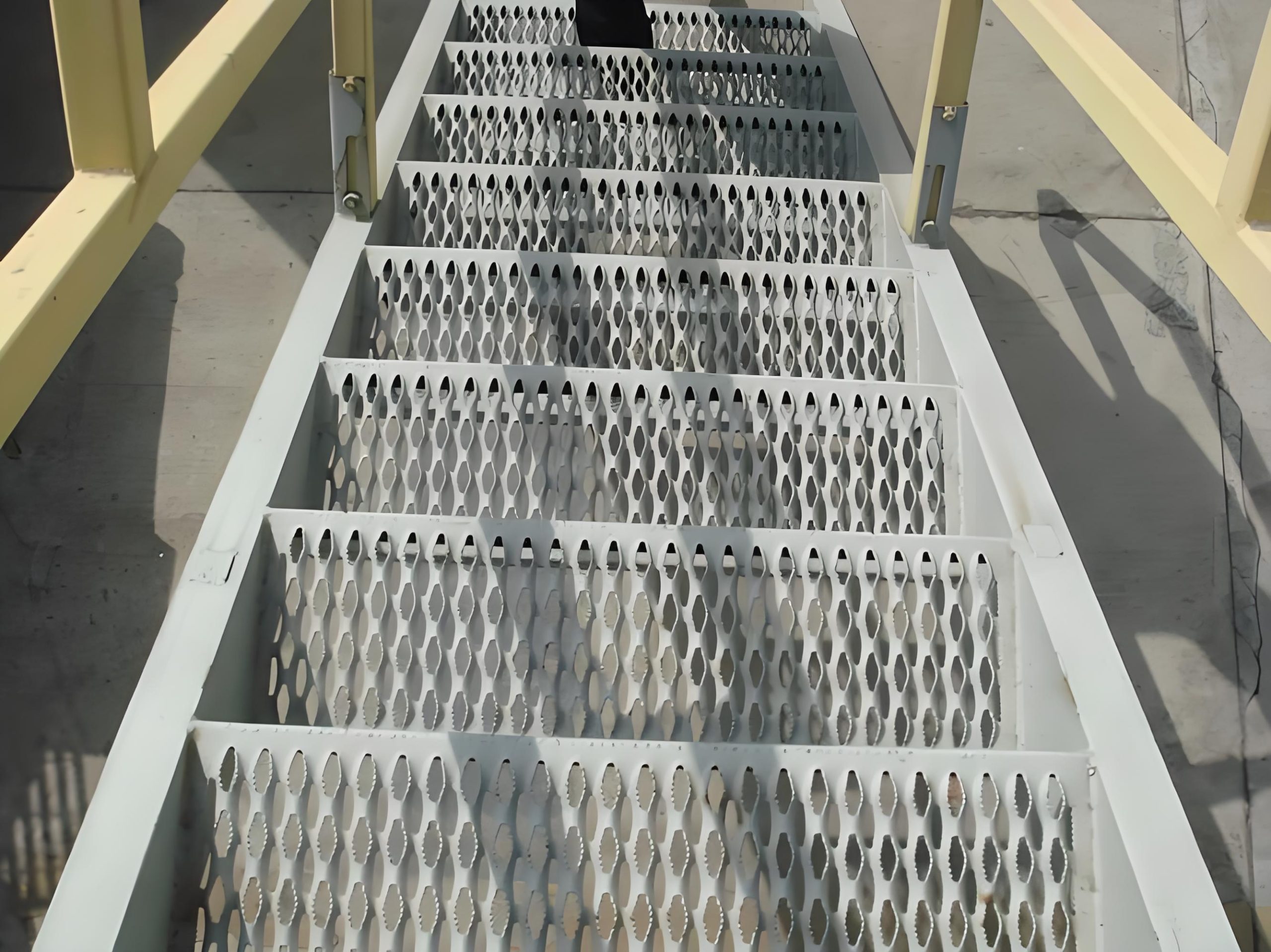
Use the following sequence when selecting steel walkway grating:
A factory quotation should include the complete specification rather than only the words “steel walkway grating.” The approved drawing should identify panel dimensions, bearing bar direction, mesh, surface, material grade, finish, tolerances, and connection details.
What is the most common size of steel walkway grating?
A 1,000 mm-wide panel with a length near 6,000 mm is a common industrial stock format, while 600, 750, 900, and 1,200 mm widths are also widely used. The most suitable size depends on the support layout, walkway width, lifting limits, and the amount of cutting required on site.
What bearing bar size is suitable for a steel walkway?
Short-span light walkways may use 25 × 3 mm or 30 × 3 mm bearing bars, while longer spans, concentrated loads, and equipment platforms may require 32 × 5 mm, 40 × 5 mm, or larger bars. The correct size must be verified with the supplier’s load table for the actual clear span and support condition.
What is the difference between 11W4 and 19W4 grating?
11W4 generally uses an 11/16-inch bearing bar pitch, approximately 17.5 mm, with 4-inch cross bar spacing. 19W4 uses a 1-3/16-inch bearing bar pitch, approximately 30.2 mm, with the same 4-inch cross bar spacing. 11W4 has a closer mesh and smaller opening, while 19W4 is closer to a 30 × 100 mm metric pattern.
