

30/100 steel grating is a common metric bar grating configuration used for industrial walkways, platforms, stair treads, drainage covers, trench grates, equipment access floors, and maintenance areas. The notation “30/100” normally describes the center-to-center spacing of the bearing bars and cross bars, but it does not define the complete grating specification. Bearing bar height, thickness, material, panel dimensions, surface type, support span, design load, finish, and fastening method must also be stated before a supplier can manufacture the correct product. This guide explains what 30/100 means, how to estimate weight per square meter, how dimensions affect structural performance, and how to choose the right 30/100 grating for a project.
Steel grating is an open grid structure made from parallel load-bearing bars connected by cross bars. The bearing bars carry the primary bending load and must span between the supports. Cross bars maintain the spacing of the bearing bars, distribute movement across the panel, and provide stability.
A 30/100 grating has a relatively close bearing bar spacing of 30 mm and a cross bar spacing of 100 mm. This combination creates a firm walking surface with useful open area for drainage and ventilation. It is often selected where the project needs a balance between foot comfort, small-object retention, load distribution, and material economy.
However, two products marked “30/100” can have very different performance. A 25 × 3 mm bearing bar and a 40 × 5 mm bearing bar can use the same 30/100 mesh while having very different weight, span capacity, stiffness, and price. The notation is therefore only one part of a complete specification.
In a typical purchase description, the full requirement may be written as:
Welded steel grating, 30/100 mesh, 30 × 5 mm bearing bars, twisted square cross bars, serrated surface, hot-dip galvanized, panel size 1,000 × 6,000 mm.
This description gives the manufacturer enough information to understand the mesh, bar size, construction, surface, finish, and panel dimensions. The design load and support span should be added for structural verification.
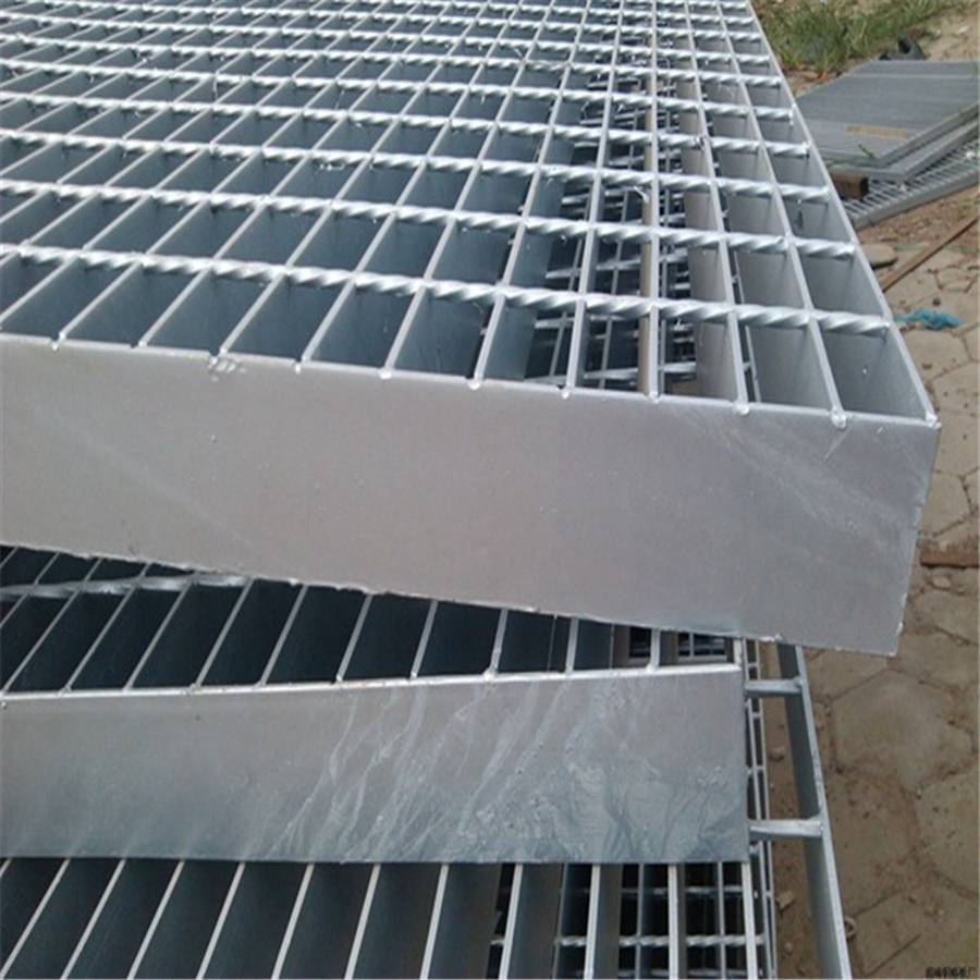
In most metric steel grating specifications, “30/100” means:
The first number normally identifies the bearing bar spacing, and the second number identifies the cross bar spacing. This convention is widely used in metric grating descriptions, although the exact notation should always be confirmed against the project drawing or applicable regional standard.
The 30 mm dimension is measured from the centerline of one bearing bar to the centerline of the next. It is not the clear opening. If the bearing bar is 5 mm thick, the theoretical opening between bars is approximately 25 mm before considering dimensional tolerances, coating, edge shape, or serrations.
A closer bearing bar spacing generally provides:
The 100 mm dimension is measured between the centers of adjacent cross bars. It is a common industrial spacing that provides panel stability while retaining a substantial open area for drainage, ventilation, and light transmission.
Reducing cross bar spacing to 50 mm can make a panel feel more rigid and can help retain smaller objects, but it generally increases material use, fabrication time, and weight. Increasing cross bar spacing may reduce cost, but the manufacturer must confirm panel stability and compliance with the project requirements.
The 30/100 designation does not identify:
For a broader explanation of mesh notation and bar sizes, see the CSSP guide to steel bar grating dimensions and specifications.
There is no single universal panel dimension for 30/100 grating. Panel sizes are selected according to the support layout, transportation limits, lifting method, installation sequence, and the manufacturer’s production capability.
| Dimension Item | Typical Selection Range | What Must Be Confirmed |
|---|---|---|
| Mesh designation | 30/100 mm | Whether both dimensions are center-to-center measurements |
| Bearing bar height | 25, 30, 32, 40, 50 mm and other project-specific sizes | Required span capacity and deflection limit |
| Bearing bar thickness | 3, 4, 5, 6 mm and other available thicknesses | Load, corrosion allowance, impact, and fabrication requirements |
| Panel width | Often 500–1,000 mm for standard industrial panels | Support arrangement, handling, and installation access |
| Panel length | Often up to approximately 6,000 mm, subject to production and shipping | Span direction, transport, lifting, and project layout |
| Cross bar spacing | 100 mm standard; closer spacing may be available | Object retention, stability, appearance, and cost |
| Support bearing | Specified by the structural designer | Minimum bearing length, frame width, and fixing details |
These are common planning values rather than guaranteed standard sizes. Custom panel dimensions are frequently produced for trenches, platforms, stairs, tanks, and equipment openings.
The bearing bar is the most important dimensional component in a steel grating panel. Its height has a strong effect on section modulus and bending stiffness, while its thickness affects cross-sectional area, local durability, and resistance to impact and wear.
| Bearing Bar Size | Typical 30/100 Use | General Characteristics |
|---|---|---|
| 25 × 3 mm | Light pedestrian walkways and short spans | Lower weight and economical for modest loads |
| 25 × 5 mm | Short-span platforms and access areas | More section thickness and impact resistance than 25 × 3 mm |
| 30 × 3 mm | General industrial walkways | Balanced weight and stiffness for moderate spans |
| 30 × 5 mm | Industrial platforms, trench covers, and heavier pedestrian loads | Higher stiffness and greater unit weight |
| 32 × 5 mm | Medium- to heavy-duty applications | Useful where additional depth is required |
| 40 × 5 mm | Heavy platforms and longer spans | Higher load capacity but greater weight and cost |
| 50 × 5 mm or heavier | Heavy-duty access covers and vehicle-related areas | Requires engineered load and support calculations |
The same 30/100 mesh may therefore be a lightweight walkway panel or a heavy-duty trench cover depending on the bearing bar selected.
Increasing bearing bar height is often an efficient way to improve bending stiffness because the material is placed farther from the neutral axis. Increasing thickness also improves capacity, but it adds weight and may have a different effect on the section properties.
The supplier should select the bar size using the clear span, load type, allowable deflection, support condition, and applicable design standard. A generic “30/100 grating” load claim without bearing bar dimensions is incomplete.
In corrosive or abrasive areas, thickness may be selected partly for durability. This should not be confused with a formal corrosion allowance. Localized pitting can be more critical than uniform thickness loss, so the material and surface treatment must also match the environment.
Cross bars may be round, twisted square, plain square, or another approved profile. They can be welded, pressed, or mechanically locked into the bearing bars.
Twisted square cross bars are common in welded grating. Their shape provides a visual texture and can contribute to the panel’s lateral stability. The twist may also improve the appearance of the open grid and help reduce sharp exposed edges.
Round cross bars can provide a smooth and simple appearance. They are used in selected welded or press-locked configurations and should be checked for compatibility with the required fabrication method and load performance.
A 100 mm cross bar spacing is often adequate for general industrial grating. A 50 mm spacing may be selected when the project requires improved small-object retention, a denser visual pattern, or additional panel stability. The closer spacing increases steel consumption and may slightly reduce the open area.
Cross bars normally run perpendicular to the bearing bars. On drawings, the bearing bar direction should be marked with an arrow or a clear note. This prevents panels from being installed with the load-bearing bars running parallel to the opening.
Standard panel dimensions are chosen to simplify production, packing, transport, and installation. Common industrial panels are often approximately 1,000 mm wide and up to 6,000 mm long, but many projects require narrower or shorter panels.
For long walkways, several panels may be installed end to end. The joint should be supported and detailed so that adjacent panels do not create a trip hazard or an unsupported edge.
A complete grating drawing should allow the fabricator, engineer, installer, and inspector to understand the product without relying on assumptions.
Look for a note such as “30/100,” “30 × 100,” or “30 mm bearing bar spacing × 100 mm cross bar spacing.” Confirm that the drawing defines whether the measurements are center-to-center or clear opening dimensions.
A bearing bar note may appear as “30 × 5,” “30/5,” or “FB 30 × 5.” The drawing legend should identify whether the first number is height and the second is thickness. Do not assume the notation is identical across every manufacturer.
Panel length and width should be shown with a clear reference to the bearing bar direction. The drawing should identify overall dimensions, cutouts, notches, corner treatments, and any non-rectangular geometry.
The drawing should state plain or serrated bearing bars, carbon steel or stainless steel grade, hot-dip galvanizing or other finish, and any pickling or passivation requirement.
Check for support angles, bearing plates, clips, bolts, hinges, lifting handles, hold-downs, and anti-slip nosing. Fasteners should be specified with the correct material and corrosion compatibility.
Load information may appear on the drawing, in a load table, or in a separate calculation. It should identify uniform load, concentrated load, wheel load where applicable, clear span, and allowable deflection.
The weight of 30/100 steel grating cannot be determined from the mesh notation alone. Bearing bar size is the largest factor, followed by cross bar size and spacing, panel banding, cutouts, welds, and surface treatment.
| Bearing Bar | Mesh | Indicative Bearing-Bar Weight | Typical Finished Panel Range |
|---|---|---|---|
| 25 × 3 mm | 30/100 | Approximately 19.6 kg/m² before cross bars | Approximately 22–24 kg/m², depending on construction |
| 30 × 3 mm | 30/100 | Approximately 23.6 kg/m² before cross bars | Approximately 26–30 kg/m², depending on construction |
| 25 × 5 mm | 30/100 | Approximately 32.7 kg/m² before cross bars | Approximately 35–40 kg/m², depending on construction |
| 30 × 5 mm | 30/100 | Approximately 39.3 kg/m² before cross bars | Approximately 42–48 kg/m², depending on construction |
| 40 × 5 mm | 30/100 | Approximately 52.3 kg/m² before cross bars | Approximately 55–65 kg/m², depending on construction |
The finished ranges are planning estimates, not certified shipping weights. Some tables list black-steel theoretical weight, while others include cross bars, banding, welding material, galvanizing, or a particular panel design. The supplier should confirm the basis of the quoted weight.
For 30 × 3 mm bearing bars at 30 mm centers, the bearing-bar component can be estimated as:
7.85 × 30 × 3 ÷ 30 = 23.55 kg/m²
This calculation excludes cross bars and other components. Depending on the cross bar profile and spacing, the actual bare panel may weigh several kilograms more per square meter. A galvanized finished panel can weigh slightly more again because of the zinc coating.
Increasing either dimension increases steel volume. Thickness also affects the amount of material in every meter of bearing bar, while height has a major influence on structural stiffness.
At the same bar size, 30 mm spacing uses more bearing bars per square meter than 40 mm spacing. This is why close-mesh grating can weigh more even when each individual bar has the same dimensions.
Twisted square, round, and plain square cross bars have different cross-sectional areas. Reducing cross bar spacing from 100 mm to 50 mm increases the number of cross bars and therefore the panel weight.
Banding bars around the panel perimeter add weight. Reinforced banding around cutouts, hinged sections, lifting points, or vehicle openings adds more.
Large cutouts reduce the amount of grating material, but reinforcement, trim angles, toe plates, nosing, handles, and support frames may offset part of that reduction.
Hot-dip galvanizing adds zinc to the steel. The increase varies with surface area, steel chemistry, coating thickness, drainage holes, and the shape of the panel. Stainless pickling and passivation normally have a much smaller effect on weight than galvanizing, although polishing or additional components may affect the final shipment weight.
Wet panels, protective packing, pallets, clips, and bundled accessories can increase shipping weight even when the grating’s engineering weight remains unchanged. Request both net grating weight and gross packed weight when freight planning is important.
30/100 mesh does not correspond to one fixed load rating. A 30 × 3 mm panel over a short span can carry a different load from a 30 × 5 mm or 40 × 5 mm panel over a longer span.
Deflection limits are often set to control walking comfort, equipment alignment, drainage, appearance, and vibration. The correct limit depends on the governing project code and the designer’s criteria. A supplier should provide load tables or calculations that state the assumptions used.
Actual performance depends on the support frame as well as the grating panel. A flexible or poorly aligned frame can deflect even when the grating itself meets its calculated capacity. Support width, bearing length, intermediate beams, panel joints, and fastener locations should be included in the design review.
Trench covers frequently experience concentrated loads near the center of the opening, at wheel contact points, or around removable panel edges. A 30/100 grating selected for pedestrian traffic should not be reused for forklift or truck traffic without a new load check.
30/100 grating can be produced in several materials, each suited to different environmental and economic requirements.
| Material Option | Typical Environment | Main Benefit | Important Limitation |
|---|---|---|---|
| Untreated mild steel | Temporary indoor use or areas with a separate coating system | Lowest material cost and easy fabrication | Rapid rusting in wet or outdoor service |
| Hot-dip galvanized steel | General outdoor and industrial service | Economical corrosion protection | Zinc coating is consumed by aggressive exposure |
| 304 stainless steel | Indoor, hygienic, freshwater, and mild chemical service | Clean surface and good general corrosion resistance | Lower chloride resistance than 316 |
| 316 stainless steel | Marine, coastal, wastewater, and chloride service | Improved resistance to pitting and crevice corrosion | Higher cost and still not immune to severe immersion |
| Aluminum grating | Weight-sensitive installations | Low density and good handling convenience | Lower stiffness and different chemical compatibility |
For most structural industrial applications, the initial comparison is galvanized carbon steel versus 304 or 316 stainless steel. Aluminum and composite alternatives may be considered when low weight, electrical insulation, or special chemical resistance is more important.
Plain carbon steel grating is economical but requires paint, powder coating, galvanizing, or another protective system for most permanent outdoor and wet applications. Without protection, corrosion can quickly reduce appearance and section thickness.
Hot-dip galvanizing coats the completed steel panel with zinc. It provides barrier protection and sacrificial protection at small scratches. The coating should be inspected for coverage, bare areas, excessive runs, blocked openings, and damage from handling.
Some projects use a duplex system consisting of galvanizing plus paint or a specialized topcoat. This can improve appearance and add another barrier, but surface preparation, coating compatibility, drying time, and repair procedures must be specified.
304 can be supplied as mill finish, pickled and passivated, brushed, polished, or electropolished. The selected finish should match hygiene, appearance, cleanability, and corrosion requirements.
316 and 316L are available with similar finish options. For welded panels in marine, chemical, and wastewater applications, pickling and passivation are often important to remove heat tint and fabrication contamination.
| Surface Type | Advantages | Typical Applications | Selection Notes |
|---|---|---|---|
| Plain | Smooth appearance, easy cleaning, comfortable for normal footwear | Dry indoor platforms, architectural floors, equipment access | May become slippery when contaminated with oil, water, or grease |
| Serrated | Improved traction in wet or contaminated conditions | Outdoor walkways, stairs, wastewater, chemical plants, marine areas | Still requires drainage, housekeeping, lighting, and safe footwear |
| Special anti-slip treatment | Higher traction for specific hazards | Steep stairs, oily process areas, high-risk access routes | Confirm cleaning, wear, testing, and replacement requirements |
Surface selection is independent of the alloy. A galvanized panel can be plain or serrated, and a stainless panel can also be plain or serrated. The choice should be based on the walking environment rather than on the material alone.
30/100 grating provides an open surface that allows rainwater, washdown water, and minor spills to pass through. Serrations may improve traction but can also retain small amounts of residue if the panel is not cleaned properly. The support frame and drainage system should prevent water from pooling below the grating.
Welded grating is produced by welding cross bars to the bearing bars at every intersection or at a defined pattern. It provides good panel rigidity and is widely used for industrial floors, platforms, stairs, and trench covers.
Press-locked grating is made by pressing cross bars into notched bearing bars. It can deliver precise spacing and a clean appearance. The notches, locking depth, and panel edge treatment should be controlled during production.
Swage-locked grating uses twisted square cross bars mechanically locked into bearing bars. This construction can be suitable for architectural and industrial applications when the required load and span are confirmed.
The required standard depends on the project country and purchaser. Common references may include:
The purchase order should identify the exact standard and edition. A manufacturer should not claim general “international standard” compliance without stating which dimensional, material, welding, galvanizing, and inspection requirements apply.
Dimensional tolerances should be agreed before fabrication. A grating panel that is structurally adequate may still be difficult to install if its width, squareness, cutouts, or support bearing does not match the frame.
Pipe penetrations, columns, valves, ladders, cable trays, and equipment bases often require irregular cutouts. The drawing should show the opening size, location, edge treatment, and any reinforcement. Cutouts near the panel edge may require special banding or a separate support angle.
Banding closes the ends of bearing bars and can improve appearance, edge safety, and panel stability. Load-bearing banding may be required around large openings or where wheel loads approach the edge of a panel.
Welding and galvanizing can introduce distortion. The manufacturer should control flatness and squareness within the agreed tolerances. Panels that rock on the support frame may create trip hazards and uneven load distribution.
Stainless steel should be fabricated with clean tools and separate work areas to prevent iron contamination. Heat tint should be removed when required, and cut edges should be deburred and treated according to the corrosion environment.
After galvanizing, field drilling and cutting should be minimized. Any damaged zinc area should be repaired using an approved zinc-rich system after cleaning and preparation.
Install the bearing bars perpendicular to the support beams so that they span the opening. This is one of the most important installation checks for 30/100 grating.
The panel must have adequate bearing on each support. The required bearing length depends on the design, span, load, frame detail, and applicable standard. Supports should be level and aligned to prevent rocking or point loading.
Clips hold panels down and prevent movement caused by foot traffic, vibration, wind, thermal expansion, or equipment operation. The clip type should match the grating construction and support profile.
Bolted hold-downs may be used for removable panels or areas requiring positive restraint. Stainless fasteners are commonly used with stainless grating. For galvanized grating, compatible galvanized or coated fasteners should be selected.
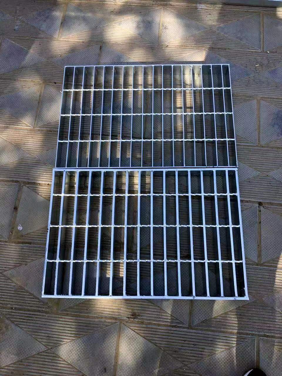
Trench covers, drainage covers, and access panels may need to be removable or hinged for inspection. Include lifting handles, locks, hinges, gas struts, or other hardware in the original specification rather than adding improvised details on site.
The close 30 mm bearing bar spacing can provide a stable walking surface and reduce the chance of small tools, heels, or wheels dropping through the panel. The 100 mm cross bar spacing maintains a familiar industrial grid while allowing water, air, and light to pass.
Where personnel, tools, or small components could fall through the grating, the opening size must be reviewed. Mesh spacing alone does not determine fall protection because bearing bar thickness, cross bar shape, support conditions, and local openings also matter.
Platforms above occupied areas or process equipment may require toe plates or kick plates to prevent tools and materials from sliding off the edge. These accessories should be shown on the drawing and attached securely to the grating or support structure.
For stairs, 30/100 grating may be combined with a serrated nosing profile to improve visual identification and traction. Tread length, width, bearing support, nosing projection, and fastening should meet the relevant stair and workplace safety requirements.
Grating improves drainage only when the supporting trench, frame, and surrounding floor are correctly graded. Debris, sediment, cable ties, packaging, and process residue can block the open area. Maintenance access should be provided so that panels can be lifted or hinged for cleaning.
30/100 grating is commonly used for elevated walkways around production equipment, pipe racks, tanks, conveyors, and maintenance zones. The close bearing bar spacing provides a firm walking surface, while the open grid reduces standing water.
Platforms require a complete review of personnel loads, stored materials, equipment loads, support spans, handrails, toe plates, and access stairs. The grating panel should be selected together with the supporting steel frame.
30/100 grating can be fabricated into stair treads with serrated surfaces, nosing, end plates, and bolt holes. Tread dimensions should be coordinated with the stair stringers and local safety requirements.
The mesh is suitable for many pedestrian trench covers and drainage channels. If vehicles or forklifts cross the trench, the bearing bar size, support span, frame, and wheel-load calculation must be upgraded accordingly.
Applications include pump stations, screening areas, clarifiers, aeration structures, channels, chemical dosing zones, and maintenance platforms. Material selection may range from galvanized steel in mild areas to 316L stainless steel in chloride or chemical exposure zones.
30/100 grating can be used around boilers, turbines, transformers, cable trenches, cooling systems, and service platforms. High-temperature areas, oil contamination, fire access, and chemical cleaning requirements should be included in the specification.
Stainless 304 or 316 grating is often selected where washdown, cleanability, and product contamination control are important. The grade should be matched to salt, acid, sanitizer, and temperature exposure.
316 or 316L serrated grating is commonly considered for docks, seawater systems, offshore platforms, coastal access stairs, and salt-spray-exposed equipment areas. Severe immersion conditions require additional corrosion review.
State whether the panel is a walkway, platform, stair tread, trench cover, drainage grate, removable access panel, or vehicle cover. The application determines the relevant loads, safety details, and fabrication requirements.
Identify moisture, salt, chlorides, chemicals, temperature, humidity, washdown frequency, biological deposits, and atmospheric contamination. Specify whether the panel is indoors, outdoors, coastal, marine, chemical, hygienic, or wastewater-related.
Measure the unsupported distance between the actual supports. Do not use the overall trench width if the frame includes bearing angles or intermediate beams.
Use load tables or an engineering calculation to choose the bearing bar height and thickness. Typical options include 25 × 3 mm, 30 × 3 mm, 30 × 5 mm, 32 × 5 mm, and 40 × 5 mm, but the correct size depends on span and load.
Select plain grating for dry, clean areas where smooth cleaning and appearance are priorities. Select serrated grating for wet, oily, muddy, sloped, outdoor, chemical, marine, or wastewater areas.
Use untreated or galvanized carbon steel for economical general service. Use 304 or 304L stainless steel for mild corrosion and hygienic applications. Use 316 or 316L for chloride, marine, wastewater, and more aggressive chemical conditions. Specify galvanizing, passivation, brushing, polishing, or other finishing requirements.
Show pipe openings, columns, ladders, hinges, handles, toe plates, kick plates, nosing, support angles, lifting points, and panel joints on the drawing.
Ask for a product drawing, load table or calculation, material certificate, coating or passivation information, dimensional inspection, welding quality records, and packing list where the project requires traceability.
When a project requires a different mesh, bar size, or surface, the product should be compared using complete specifications rather than a short designation alone. A supplier can then verify weight, load capacity, fabrication feasibility, and installation details before production.
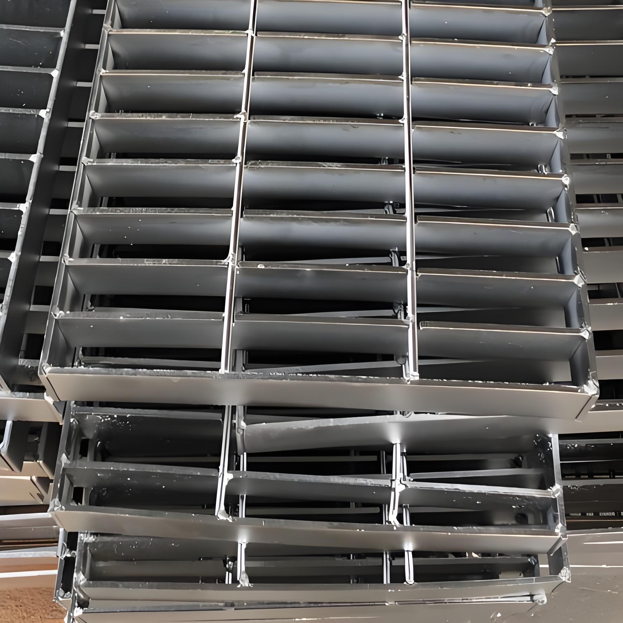
What does 30/100 mean in steel grating? It normally means 30 mm center-to-center spacing between the bearing bars and 100 mm center-to-center spacing between the cross bars. It does not specify the bearing bar height, thickness, material, panel size, surface finish, load capacity, or corrosion protection. A complete specification must include these details.
How much does 30/100 steel grating weigh per square meter? The weight depends mainly on the bearing bar size. As an indicative guide, 25 × 3 mm may produce a finished panel of about 22–24 kg/m², 30 × 3 mm about 26–30 kg/m², 30 × 5 mm about 42–48 kg/m², and 40 × 5 mm about 55–65 kg/m². Actual weight varies with cross bars, banding, cutouts, galvanizing, and the manufacturer’s calculation basis.
Is 30/100 steel grating suitable for heavy loads? It can be suitable for heavy loads when the bearing bar size, span, support frame, and loading condition are engineered correctly. The 30/100 mesh alone does not define a heavy-duty rating. Vehicle, forklift, impact, or long-span applications require a specific load calculation or verified load table.